Rosemount Model 8732C Integral Mount Magnetic Flowmeter System
5-4
Software Testing
Loop Test The Loop Test drives the transmitter output to a desired electrical
current output on the 4–20 mA terminals. This capability allows
you to check the entire current loop prior to start-up. On the LOI the
test quits after five minutes if the transmitter is not returned
to normal operation manually.
Pulse Output Test The Pulse Output Test allows you to drive the frequency output
at digital output terminals to a desired value. This capability allows
you to check auxiliary equipment prior to start-up. On the LOI the test
quits after five minutes if the transmitter is not manually returned to
normal operation.
Transmitter Test The Transmitter Test initiates a series of diagnostic tests that are not
performed continuously during normal operation. It performs the
following tests:
• Display Test
• RAM Test
•PROM Test
During the entire transmitter test, all outputs are driven to full-scale:
20 mA and 1,000 Hz. The test requires about 10 seconds to complete.
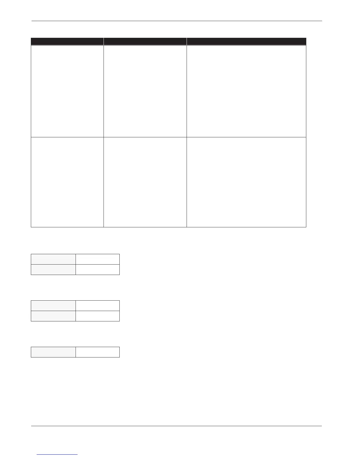
Symptom Potential Cause Corrective Action
Noisy Process. Chemical additives upstream of
magnetic flowmeter.
Complete the Noisy Conditions Basic Procedure (page 5-3).
Move injection point downstream of magnetic flowmeter, or
move magnetic flowmeter.
Sludge flows–Mining/Coal/Sand/
Slurries (other slurries with hard
particles).
Decrease flow rate below 10 ft/s.
Styrofoam or other insulating particles in
process.
Complete the Noisy Conditions Basic Procedure (page 5-3).
Consult factory.
Electrode coating. Use replaceable electrodes in Model 8705.
Use a smaller flowtube to increase flow rate above 3 ft/s.
Periodically clean flowtube.
Air in line. Move the flowtube to another location in the process line to
ensure that it is full under all conditions.
Meter output is unstable. Electrode incompatibility. Check Magnetic Flowmeter Material Selection Guide
(00816-0100- 3033) for chemical compatibility with
electrode material.
Improper grounding. Check ground wiring. See on page 2-14 for wiring and
grounding procedures.
High local magnetic or electric fields. Move magnetic flowmeter (20–25 ft. away is usually
acceptable).
Control loop improperly tuned. Check control loop tuning.
Sticky valve (look for periodic oscillation
of meter output).
Correct valve sticking.
Flowtube failure. Perform Flowtube Tests A, B, C, and D on page 5-5.
Analog output loop problem. Check that the 4–20 mA loop matches the digital value.
Perform analog output test.
TABLE 5-2. Advanced Troubleshooting–Model 8732C.
HART Fast Keys
1, 2, 2
LOI
Transmitter Test
HART Fast Keys
1, 2, 3
LOI Transmitter Test
HART Fast Keys
1, 2, 1, 2