2-25
Installation
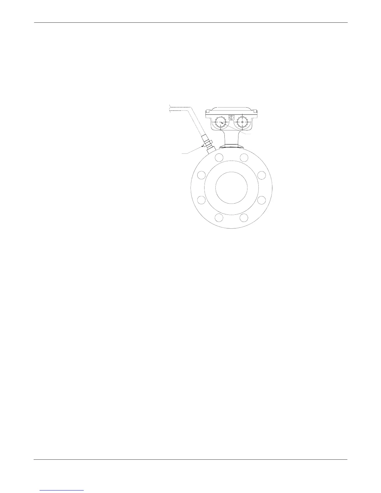
Relief Valves
Housing configuration “W1” provides a relief valve in the housing to
prevent possible overpressuring caused by damage to the lining or
other situations that might allow process pressure to enter the housing.
The relief valve will vent when the pressure inside the flowtube
housing exceeds 5 psi. Additional piping (provided by the user) may be
connected to this relief valve to drain any process leakage to safe
containment (see Figure 2-28). In the event of a process leak, these
models will not protect the coils or other sensitive areas of the
flowtube from exposure to the pressure fluid.
¼ NPT
Optional:
Plumb to an area consistent
with the type of process
¾–14 NPT Conduit
Connection
8705-0021A05B
FIGURE 2-28. Relief Valve Venting.