Rosemount Model 8732C Integral Mount Magnetic Flowmeter System
2-20
OPTIONS,
CONSIDERATIONS,
AND PROCEDURES
If your application of the Model 8732C includes an externally powered
4–20 mA loop, auxiliary output control or pulse output, certain
requirements may apply in addition to those previously listed.
Satisfy these requirements before attempting to install and operate
the Model 8732C.
Connect 4–20 mA Loop
External Power Source
The 4–20 mA output loop is powered either internally or externally.
Internal
The loop may be powered from the transmitter itself. Resistance in the
loop must be 1,000 ohms or less. If a HART-based communicator or a
distributed control system (DCS) is used, it must be connected across a
minimum of 250 ohms resistance in the loop.
External
External power must be supplied if the Model 8732C is to be used in a
multidrop installation (see Multidrop Communications on page
4-18). A 10–30 V dc power source is required. If a HART-based
Communicator or DCS is used, it must be connected across a
minimum of 250 ohms resistance in the loop.
If your application uses the external power option for the 4–20 mA
loop, complete the following steps to connect the power source to
the transmitter:
1. Ensure that the power source and connecting cable meet the
requirements outlined above and in Electrical Considerations
on page 2-5.
2. Turn off the transmitter and analog loop power sources.
3. Run the power cable into the transmitter.
4. Connect – dc to terminal – 4–20 mA.
5. Connect + dc to terminal + 4–20 mA.
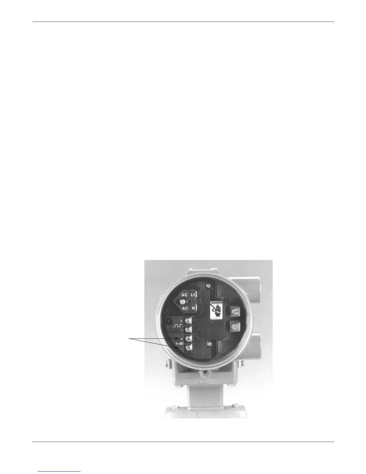
FIGURE 2-25. 4–20 mA
Loop Power Connections.
4–20 mA
Outputs
8732-005AB