2-5
Installation
Electrical Considerations
Before making any electrical connections to the Model 8732C, consider
the following standards and be sure to have proper power supply,
conduit, and other accessories.
Conduit Connections The Model 8732C Integral Mount Magnetic Flowmeter Transmitter
has two ¾–inch NPT conduit connections. If one of these ports is
not being used, it must be sealed with a conduit seal. In some
cases, conduits may also require drainage if moisture could build up in
the line.
Transmitter Input Power The Model 8732C Transmitter is designed to be powered by voltages
ranging from 90 to 250 V ac (50 to 60 Hz) or 15–30 V dc. Units powered
with an ac power supply should be connected to standard ac
connections for 90 V ac or 250 V ac. Units powered by a 15–30 V dc
power supply have special considerations.
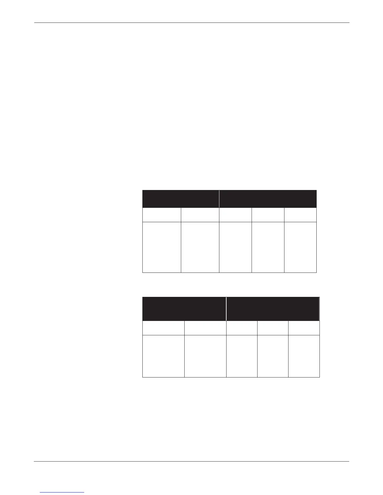
DC Power Requirements Units powered with 15–30 V dc may draw up to 2 amps of current. As a
result, the input power wire must meet certain gauge requirements.
Table 2-1 and Table 2-2 show the maximum wire length for
corresponding supply voltages, wire gauges, and wire type.
TABLE 2-1. Length of Annealed
Copper Wires.
TABLE 2-2. Length of Hand-drawn
Copper Wires.
Types of
Power Supply Wires
Maximum Length of the Wire for Each
Corresponding Power Supply Source
Wire Gauge Milliohms/ft
Annealed Cu
30 V
Supply (ft)
24 V
Supply (ft)
20 V
Supply (ft)
20 10.15 1,230 625 365
18 6.385 1,955 990 585
16 4.016 3,110 1,580 930
14 2.525 4,950 2,515 1,485
12 1.588 7,870 3,995 2,360
10 0.999 12,510 6,355 3,750
Types of
Power Supply Wires
Maximum Length of the Wire for
Each Corresponding Power Supply
Source
Wire Gauge Milliohms/ft
Hand-drawn Cu
30 V
Supply (ft)
24 V
Supply (ft)
20 V
Supply (ft)
18 6.640 1,880 955 565
16 4.176 2,990 1,520 895
14 2.626 4,760 2,415 1,425
12 1.652 7,565 3,840 2,270
10 1.039 12,030 6,110 3,605