Rosemount Model 8732C Integral Mount Magnetic Flowmeter System
2-6
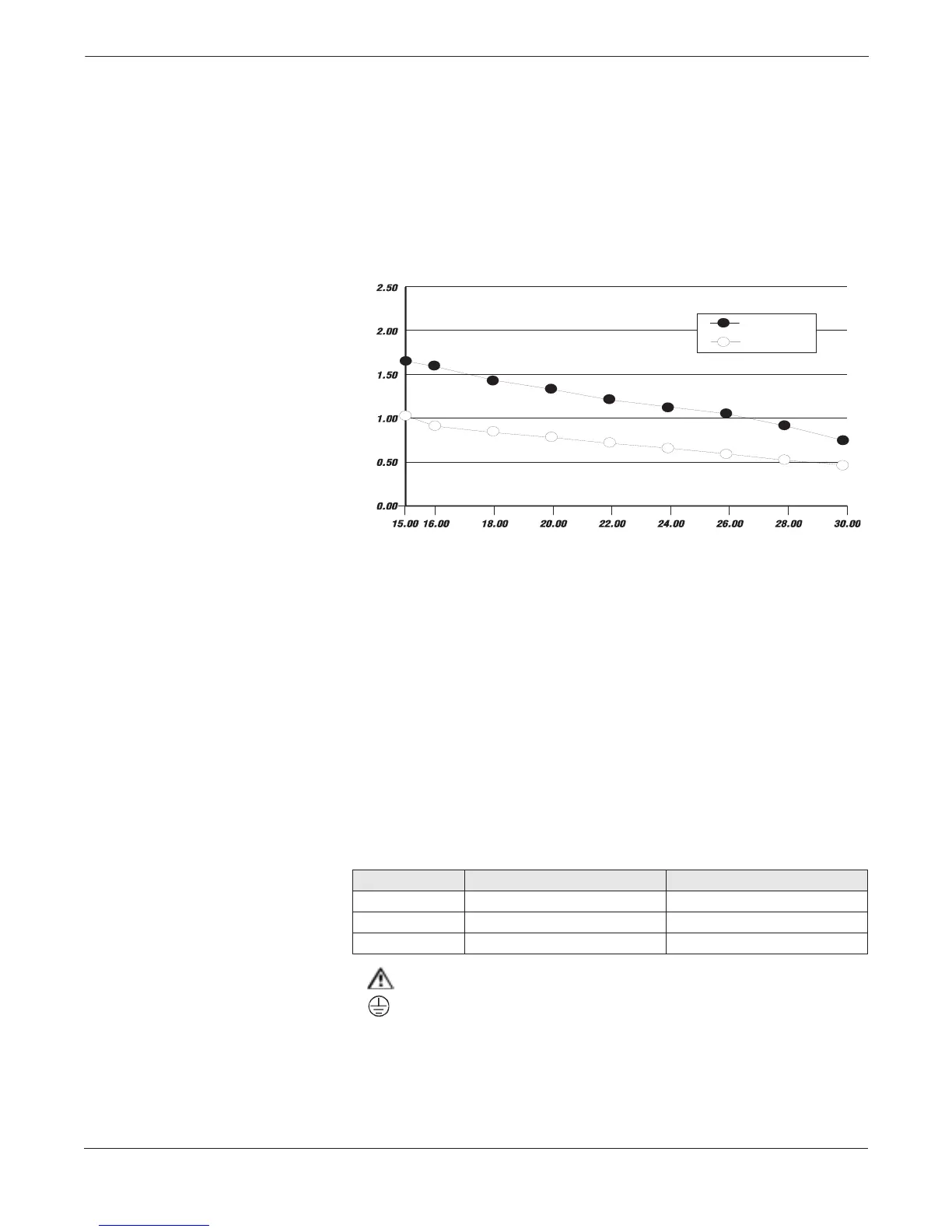
Figure 2-3 shows the surge current for each corresponding supply
voltage. For combinations not shown above, you can calculate the
maximum distance given the surge current, the voltage of the source,
and the minimum start-up voltage of the transmitter, 15 V dc using the
following equation:
Max. Resistance = (Supply Voltage –15 V dc) / Surge Current
Use Tables 2-1 and 2-2 to determine the maximum wire length
allowable for your power supply and maximum resistance.
IMPORTANT USER NOTES
Installation Category
Installation (Overvoltage) Category II.
Supply Wire Requirements
12- to 18-gauge wire. For connections in ambients in excess of 60° C
(140° F), use wire rated to at least 90° C (194° F).
Disconnects
The supply wires should be connected to the device through an external
disconnect or circuit breaker. The disconnect or circuit breaker should
be clearly labeled and located near the transmitter.
Overcurrent Protection
Model 8732 requires overcurrent protection of the supply lines.
Maximum rating of overcurrent devices are as follows:
Transmitter Symbols
Caution Symbol — Check product documentation for details.
Protective conductor (grounding) terminal.
Surge
Nominal
Supply Current (Amperes)
Input Voltage (Volts)
FIGURE 2-3. Supply Current vs.
Input Voltage.
Power System Fuse Rating Manufacturer
110 V ac 250 V; 1 Amp, Quick Acting Bussman AGCI or Equivalent
220 V ac 250 V;.5 Amp, Quick Acting Bussman AGCI or Equivalent
15 to 50 V dc 250 V; 3 Amp; Quick Acting Bussman AGCI or Equivalent