Do you have a question about the Rosslare AC-Q41HB and is the answer not in the manual?
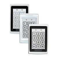
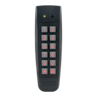
Details the different AC-Q4x series models, specifying their features like PIN only, proximity card, and piezoelectric contacts.
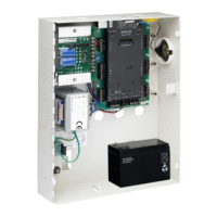
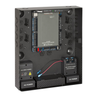
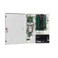
Lists all items included in the controller package, ensuring users check for completeness upon receipt.
Outlines optional equipment like lock strike mechanisms, power supplies, REX buttons, and sounders needed for installation.
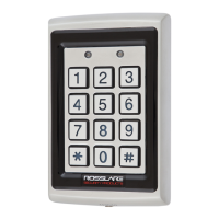
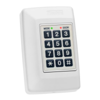
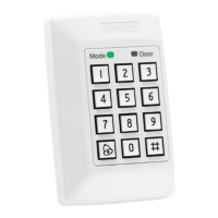
Identifies and explains the controls and indicators on the controller's front panel, including LEDs and the keypad.
Provides step-by-step instructions for physically installing the controller, including drilling hole identification and mounting procedures.
Explains the wiring process for both pre-wired cable models and terminal block models, referencing diagrams for connections.
Describes the three operational modes (Normal, Secure, Bypass) and how they are indicated by the controller's LED.
Defines the three user levels (Normal, Secure, Master) and their access rights based on code assignments.
Details the procedures for changing the controller's operational mode between Normal, Secure, and Bypass states.
Explains how the auxiliary input and output can be configured in 10 different modes for enhanced usability.
Describes the function and typical placement of the Request-to-Exit (REX) button for internal door access.
Covers the tamper detection mechanism that triggers an alert upon unauthorized opening or removal of the controller.
Explains the lockout function triggered by multiple incorrect code entries, disabling the keypad and reader.
Details the features and operation of the BL-D40 external sounder, including its alerts and communication protocols.
Guides on how to enter the programming mode using the keypad and the default programming code.
Explains the process to exit programming mode, including auto-exit conditions and confirmation beeps.
Details the procedure to change the Open code, used primarily for testing the lock strike relay during installation.
Guides on modifying the Auxiliary code, which is used for testing the auxiliary relay in specific modes.
Explains how to change the controller's main programming code, stressing that it cannot be erased.
Details the process for changing the Normal/Secure code, noting its interaction with auxiliary input priority.
Covers changing the Normal/Bypass code, which also controls the door chime function.
Explains how to set Fail Safe/Secure operation, tamper siren duration, and lock strike release times using a specific code format.
Details configuring the auxiliary input/output across 10 distinct modes for varied functionality.
Describes the built-in keypad heater's automatic activation and its benefits for low-temperature operation.
Guides on configuring the lockout feature by defining the number of wrong attempts and the duration of the lockout.
Explains how to customize the controller's backlight behavior, including options for dimming and timed activation.
Details the methods and rules for enrolling primary and secondary user codes, including code uniqueness and system code restrictions.
Outlines the procedures for deleting user codes using standard or code search methods, erasing both primary and secondary codes.
Explains how to assign specific relay codes to users for controlling the Lock Strike and Auxiliary relays.
Describes how to change PIN code length, which also resets all memory and codes to factory defaults.
Guides on how to replace the controller's programming code using the REX button and the initial default code.
Details the procedure for replacing the Normal/Secure code, requiring the controller to be in Secure mode.
| Brand | Rosslare |
|---|---|
| Model | AC-Q41HB |
| Category | Controller |
| Language | English |