Installation
16 AC-Q4x Series Installation and Programming Manual
3.2.1 Pre-wired Models
These units are supplied with a 10-conductor 60-cm (24-in.) pigtail
(24-AWG cable) with exposed wires coated with solder.
To wire the controller:
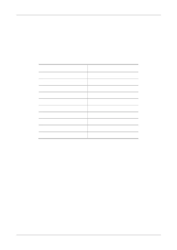
1. Select the appropriate connections according to Table 1.
Table 1: Wire Color Guide
Color Description
Red V input
Black Ground
Green REX/BL
White In/Monitor
Purple Lock: Com
Gray Lock: N.O.
Brown Lock: N.C.
Blue Aux: Com
Yellow Aux: N.O.
Orange Aux: N.C.
2. Prepare the secured power supply’s cable by cutting the cable
jacket back 3.2 cm (1¼”) and strip the wire 1.3 cm (½”).
3. Splice the controller pigtail wires to the corresponding ancillary
devices and insulate each connection, including unused wires.
Refer to the wiring diagrams, depending on the desired
application:
Wiring the Lock Strike Relay & REX (Figure 3)
Wiring for Auxiliary Input & Output (Figure 4)
Wiring for the BL-D40 External Sounder (Figure 5)
 Loading...