43
Use Approved hydraulic oils(see 9.4 ).
disconnect switch and emergency stop buttons
are in the “ON” position. Proceed with the
following steps.
Only skilled and authorized personnel
should be allowed to perform these operations.
Carefully follow all instructions shown below to
prevent possible damage to the car lift or risk of
injury to people.
Be sure that the operating area is cleared of
and performing electric and hydraulic
connections, the lift can be operated by following
1. Verify both top limit switches and stop down
switch electrical connections are complete, as
shown in Fig. 18 and Fig. 19.
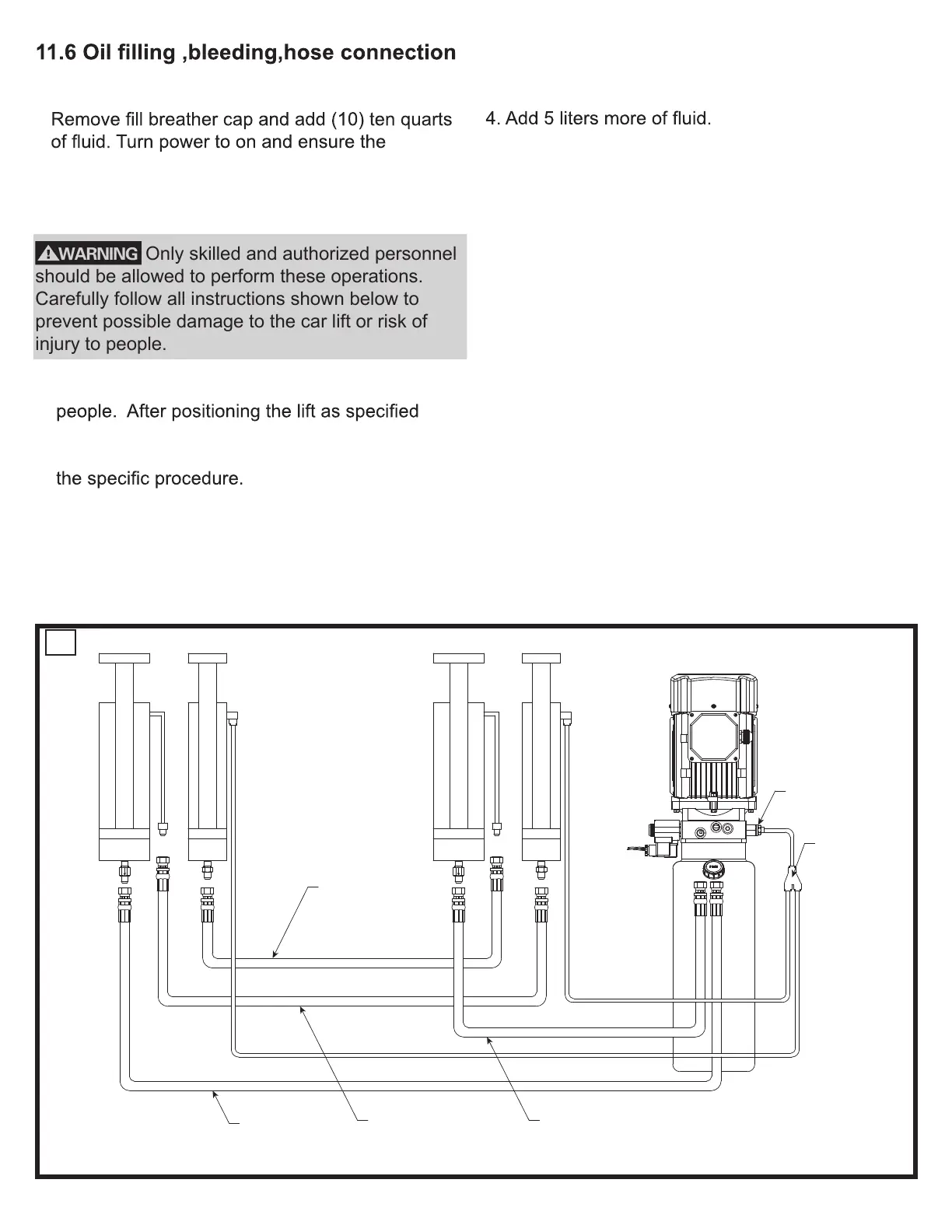
2. Connect hydraulic hoses “A” and “B” to the power
unit as shown in Fig. 20.
3. Push the “UP” button until both platforms stop
moving.
5. Connect the uninstalled hydraulic hoses marked
“C” and “D”, as shown in Fig. 20.
6. Connect the uninstalled hydraulic tube, as shown
in Fig. 20.
7. Push the “UP” button until both platforms stop
moving.
8. Open the cabinet lid and press the “Override
UP” button and UP button (Top of control panel),
as shown in Fig. 21, also HOLD FOR
APPROXIMATELY 40 SECONDS.
9. Close cabinet lid and lower platforms to the
ground.
If lift does not raise but the motor runs, check the
motor for proper direction of rotation and switch
the phases on the power supply line if necessary.
20
Hose A
DSS35-9801-1L(DS35EX)
DSS35-9801-1(DS35)
Hose B
DSS35-9801-2L(DS35EX)
DSS35-9801-2(DS35)
Hose D
DSS35-9801-4L(DS35EX)
Hose C
DSS35-9801-3L(DS35EX)
Power
Unit
EPL8-03
EPY8
Y FITTING
DSS35-9801-3S (DS35)
DSS35-9801-4S(DS35)