13
CHAPTER 4 -
INSTALLATION
KAPITEL 4 -
INSTALLATION
ENTFERNEN SIE VOR INSTALLATION DER HEBEBÜHNE
ALLE VERPACKUNGSTEILE UND ÜBERPRÜFEN SIE DIE
WARE
DIE HEBEBÜHNE DARF NUR VON SPEZIALISIERTEN TECH-
NIKER INSTALLIERT WERDEN, DIE DURCH DEN HERSTELLER
ODER EINEN AUTHORISIERTEN HÄNDLER MIT DIESER AUF-
GABE BETRAUT WURDEN. DIE NICHTBEACHTUNG DIESER
VORSCHRIFT KANN ZU SCHWERWIEGENDEN SCHÄDEN
BEI PERSONEN ODER GEGENSTÄNDEN FÜHREN.
Bei der Installation der Hebebühne muss der Sicherheitsabstand von
Wänden, Säulen, anderen Maschinen usw. eingehalten werden.
Die Mindesthöhe des Raumes muss wenigsten 4500 mm betragen.
Berücksichtigt man den normalerweise notwendige Arbeitsraum,
den Platz, den die zentrale Bedienungseinheit beansprucht, und
Fluchtwege für den Notfall, sollte der Mindestabstand zu den
Wänden nicht unter 1500 mm liegen. (siehe Abb. 8).
ARBEITSSCHRITTE FÜR DIE INSTALLATION
1. Positionierung der Hebebühne.
2. Kontrolle ob, Stromanschlüsse zur Verfügung stehen.
3. Ölhydraulische Anschlüsse
4. Anschluss an das Stromnetz.
5. Zementbasis und Heberbefestigung.
6. Erstmaliges Starten.
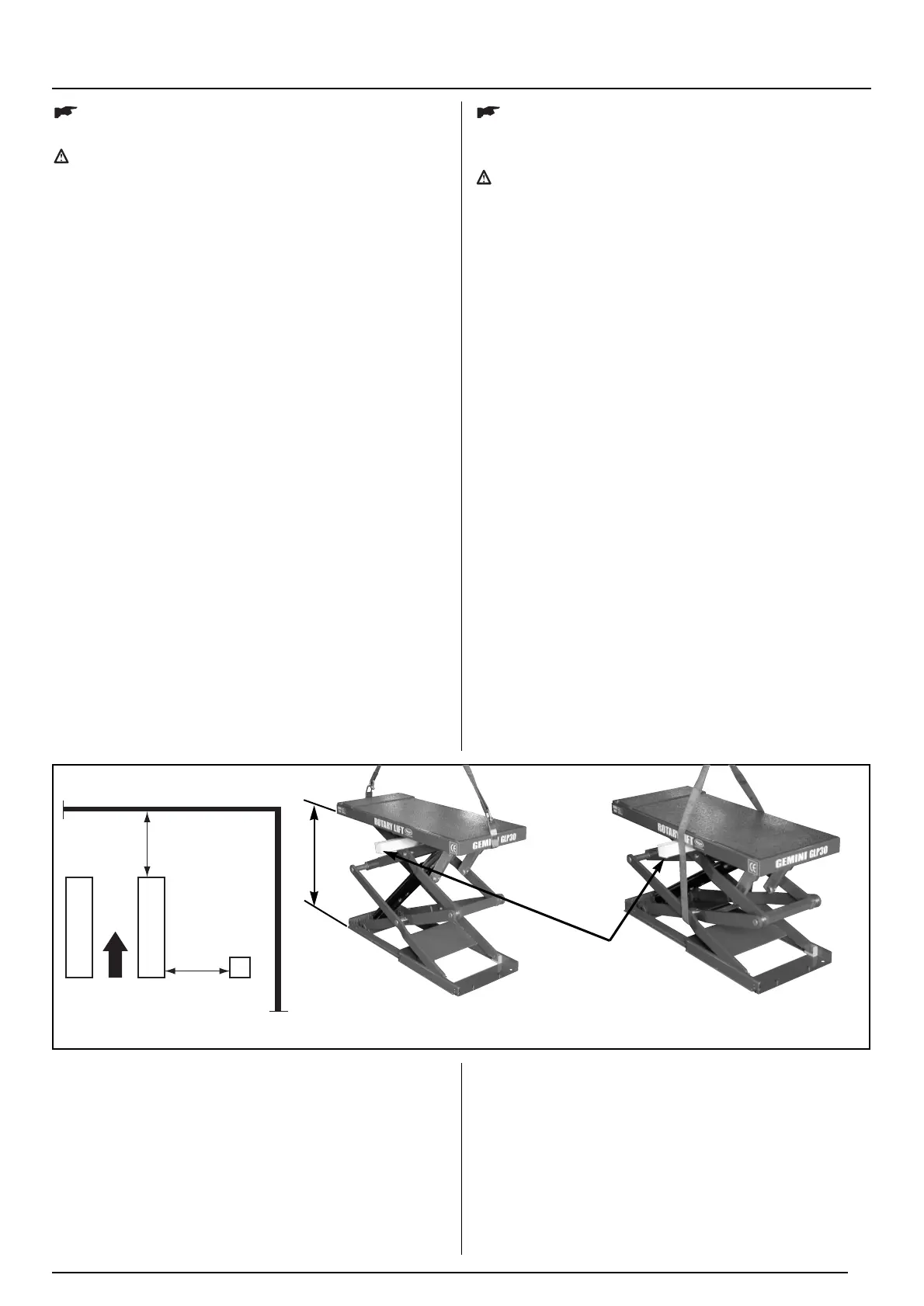
1) POSITIONIERUNG DER HEBEBÜHNE
h 4500 min.
min.
min.
Positionieren Sie die Hebebühne mit Hilfe eines Gerüstwagens
oder einem anderen geeigneten Lastenheber an der gewün-
schten Stelle. Ziehen Sie (zum Öffnen der Hebebühne) mit
einem Kran die beiden Konsolen wie in der Abbildung darge-
stellt, bis zu einer Höhe von 70 cm und fügen
Holzunterlegestücke zu, um das Schlieben der Brücke wäh-
rend des anseilen zu verhindern. Um die Hebebühne zu bewe-
gen, richtig positionieren. Gleichen Sie, eventuelle
Unebenheiten des Bodens mit Metallunterlegstücken aus.
UNPACK THE GOODS AND CHECK FOR POSSIBLE
DAMAGE BEFORE INSTALLING THE LIFT.
ONLY SKILLED TECHNICIANS, APPOINTED BY THE
MANUFACTURER, OR BY AUTHORIZED DEALERS
SHOULD BE ALLOWED TO INSTALL THE CAR LIFT.
SERIOUS DAMAGE TO PEOPLE OR EQUIPMENT CAN
BE CAUSED IF THIS RULE IS NOT FOLLOWED.
The lift must be installed according to the specified safe
distance from walls, columns, other equipments etc. The room
must be a minimum 4500 mm. in height. The minimum
distance from walls must be 1500 mm. take into considera-
tion the necessary space to work easily. Further space for the
control site and for possible runways in case of emergency is
also necessary. (picture 8).
INSTALLATION PROCEDURE
1. Lift location.
2. Check for power supply availability.
3. Hydraulic connections.
4. Electric network connection.
5. Concrete base and fixing of the lift.
6. Initial running.
1) LOCATION OF THE LIFT
TO OPEN
ÖFFNEN
TO MOVE
BEWEGEN
70 cm
Place the automotive lift using a crane truck or any other lif-
ting equipment in the desired position. Raise (to open the lift)
the two platforms using a crane, following the intructions in
the picture, and place them at a height of about 70 cm.
Insert a wooden shim to prevent the lift from closing during
the slinging phase. To move the car lift, sling it as described
in picture 8 and place it into the right position. Use metal
shims to level the ground where necessary.
pict. - Abb.
8
WOODEN JOIST
HOLZBALKEN

 Loading...