14
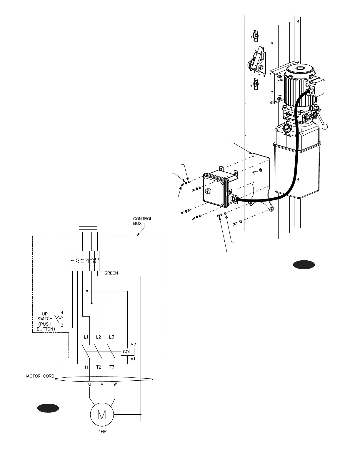
Fig. 22a
Fig. 22b
14. 3ø Control Box Installation:
A) Attach Mounting Bracket on column, as shown in Fig.
22a, using (1) 5/16”-18NC x 1/2” Socket Head Counter
Sunk Machine Screw, (2) 5/16”-18NC x 1/2” HHCS, and
(2) 5/16” Flat Washers.
B) Attach Control Box to Bracket using (4) 1/4”-20NC
x 1/2” HHCS, (4) 1/4” Flat Washers, and (4) 1/4” Star
Washers.
C) Route cord through strain relief on motor and connect
per table on the bottom of page 13.
5/16”-18NC x 1/2” HHCS
5/16” Flat Washer
1/4” Flat Washer
1/4”-20NC x 1/2” HHCS
1/4” Star Washer
Mounting Bracket
Note:
The contactor in the control box has a 480V coil.
For installations where the electric supply is 230V,
the coil must be replaced with the extra 230V coil
shipped with the control box. For 575V electric
supply, the coil must be replaced with the extra
575V coil shipped with the lift.
1 & A1 FOR
OVERHEAD SWITCH
CONNECTION
JUMP 1 & A1 IF
LIFT DOES NOT
HAVE OVERHEAD
SWITCH
AC INPUT
208-240V, 480V, OR 575V
 Loading...


