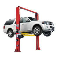
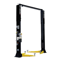
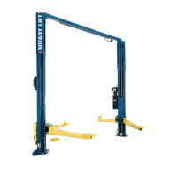
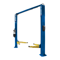
Do you have a question about the Rotary SPO16 and is the answer not in the manual?
Configure lift position in bay and set column placement using specified dimensions.
Install column extensions and adjust lift height per model specs and clearance requirements.
Attach overhead bracket, install overhead assembly, and secure column ties.
Details on concrete pad specifications and anchor bolt installation for lift stability.
Important notes regarding foundation design, concrete strength, and reinforcing steel.
Install air valve, cylinders, switches, and related components for lift operation.
Mount power unit, connect electrical supply, and install wiring and components.
Route hydraulic hoses and equalizer cables through columns and overhead assembly.
Install lift arms, pins, restraint gears, and arm stops for safe vehicle lifting.
Perform pressure tests, adjust cables, install decals, racks, and door bumpers.
Mount DC control cabinet, power unit, and battery components for DC lift models.
Connect DC control cables to motors, batteries, and disconnect switches.
Install receptacles, laser spotter, charger cables, and close cabinet covers.
Essential safety precautions, warnings, and guidelines for operating the lift.
Defines duties for qualified operators, inspectors, and maintenance personnel.
Step-by-step instructions for safely spotting, loading, and lifting vehicles.
Guidelines for daily, monthly, and semi-annual maintenance checks and lubrication.
Identifies common lift problems and provides remedies for resolution.
Procedure for safely de-energizing the lift before maintenance or repair.
List of approved accessories such as utility boxes and filter/regulator/lubricators.
Verification of ETL and CETL listing for the AC motor and compliance standards.
| Capacity | 16, 000 lbs |
|---|---|
| Power Source | Electric |
| Voltage | 460V |
| Phase | 3 |
| Load Capacity | 16000 lbs |


 Loading...