2
A
E F
B
K
D
C
H
H
G
G
J
L
A
E F
B
K
D
C
H
H
G
G
J
L
VLXS10 VLXS7
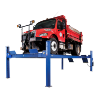
MOVEMENT OF LIFT
A Leg
1. Lift Location: Always check architect’s building plans when
applicable. The lift should be located on a relatively level floor
in a space which will allow adequate working space around
the vehicle, Fig. 1.
Note: Lift can be installed with cylinder end pointing towards
front (typical) or rear of bay. Be alert to differences in lift
clearance requirements according to installation option
chosen and customer preference.
DO NOT install on asphalt or other similar unstable
surfaces.
Note: At full rise, the lift moves the vehicle 15" (381mm), Fig. 2.
2. Remove shipping bands and wood skids from lift.
NOTE:
Lift can be installed with cylinder end pointing towards front or rear of bay. Be alert to differences in lift clearance requirements
according to installation option chosen and customer preference.
CLEARANCE AROUND VLXS10 LIFT
A. Overall Length .............................................. 7'-7" (2311mm)
B. Overall Width ................................................6'-11-3/4" (2127mm)
C. Minimum To Center Of Next Lift ...............11'-0" (3353mm)
D. Minimum To Nearest Obstruction ............. 5'-0" (1981mm)
E. Minimum For 24' (7315mm) Bay
Standard Approach (G) ...........................10'-9" (3277mm)
Optional Approach (H) ............................13'-3" (4039mm)
F. Minimum For 24' (7315mm) Bay
Standard Approach (G) ...........................13'-3" (4039mm)
Optional Approach (H) ............................10'-9" (3277mm)
G. Approach
H. Approach (Optional)
J. At Full Rise Lift Moves 15" In This Direction
K. 2" Conduit to Power Unit (Optional).
L. Width of Platform/Base .............................. 6'-6-1/2" (1994mm)
Fig. 1
Fig. 2
CLEARANCE AROUND VLXS7 LIFT
A. Overall Length .............................................. 7'-7" (2311mm)
B. Overall Width ................................................6'-11-3/4" (2127mm)
C. Minimum To Center Of Next Lift ...............11'-0" (3353mm)
D. Minimum To Nearest Obstruction ............. 5'-0" (1981mm)
E. Minimum For 24' (7315mm) Bay
Standard Approach (G) ...........................10'-9" (3277mm)
Optional Approach (H) ............................13'-3" (4039mm)
F. Minimum For 24' (7315mm) Bay
Standard Approach (G) ...........................13'-3" (4039mm)
Optional Approach (H) ............................10'-9" (3277mm)
G. Approach
H. Approach (Optional)
J. At Full Rise Lift Moves 15" In This Direction
K. 2" Conduit to Power Unit (Optional).
L. Width of Platform/Base .............................. 6'-6-1/2" (1994mm)
 Loading...