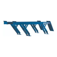
The Rotary VLXS7 and VLXS10 are low-rise car lifts designed for vehicle maintenance and repair, offering capacities of 7,000 lbs (VLXS7) and 10,000 lbs (VLXS10) respectively. These lifts are engineered to provide a stable and secure platform for vehicles, allowing technicians to access the underside of cars for various service tasks.
Function Description:
These low-rise car lifts operate hydraulically to raise vehicles to a convenient working height. The design features two main platforms that support the vehicle's chassis, with a scissor-style lifting mechanism underneath. The hydraulic system, powered by an electric motor, extends the scissor arms, elevating the platforms. Safety latches are incorporated to secure the lift at various heights, preventing accidental lowering. The lifts are designed for installation on a level concrete floor, with specific anchoring requirements to ensure stability and safe operation. The hydraulic power unit can be configured for either 115V or 208-230V single-phase electrical supply, offering flexibility based on available power.
Important Technical Specifications:
- Models: VLXS7 and VLXS10
- Capacity:
- VLXS7: 7,000 lbs (Maximum 1,750 lbs per pad)
- VLXS10: 10,000 lbs (Maximum 2,500 lbs per pad)
- Overall Length: 7'-7" (2311mm) for both models.
- Overall Width: 6'-11-3/4" (2127mm) for both models.
- Minimum to Center of Next Lift: 11'-0" (3353mm).
- Minimum to Nearest Obstruction: 5'-0" (1981mm).
- Minimum for 24' (7315mm) Bay:
- Standard Approach (G): 10'-9" (3277mm)
- Optional Approach (H): 13'-3" (4039mm)
- Width of Platform/Base (L): 6'-6-1/2" (1994mm).
- Lift Movement at Full Rise: The lift moves the vehicle 15" (381mm) in the direction of the cylinder end.
- Anchoring Requirements:
- Concrete Strength: Minimum 3,000 PSI (20N/mm²).
- Concrete Thickness: Minimum 4-1/4" (108mm) for 3-1/4" (83mm) anchor embedment.
- Anchor Bolts: 3/4" diameter, 5-1/2" long anchors for the lift. 1/2" diameter anchors for the power unit mounting post and ramps.
- Anchor Torque: 150 ft-lbs (203 N-m) for lift anchors.
- Spacing: Anchors must be at least 5-11/16" (145mm) from any edge or seam in the concrete.
- Power Unit Electrical Requirements:
- Single Phase 115V 60Hz: Running motor voltage range 103-127 Volts. Requires a 25 amp fuse.
- Optional Single Phase 208-230V 60Hz: Running motor voltage range 197-253 Volts. Requires a 20 amp circuit.
- Hydraulic Fluid: Dexron III ATF or hydraulic oil that meets ISO 32.
Usage Features:
- Installation Flexibility: The lift can be installed with the cylinder end pointing towards either the front or rear of the bay, allowing for adaptation to different shop layouts and customer preferences. This flexibility, however, requires careful consideration of clearance requirements.
- Approach Options: The lift supports both standard and optional approaches, accommodating various vehicle types and service needs.
- Safety Latches: The lift incorporates safety latches to hold the vehicle securely at elevated positions, enhancing user safety during maintenance.
- Ramp Positioning: Ramps are positioned to provide a minimum of 1/2" (13mm) clearance between the ramp and the front edge of the pad, and 5/8" (16mm) clearance between the outside surfaces of the pad and the inside surface of the ramps.
- Wheel Spotting Dish: A wheel spotting dish helps guide the vehicle into the correct position on the lift platforms.
- Hose Routing Options: Hydraulic hoses can be routed either through a 2" conduit embedded in the concrete or using a hose guard, depending on the installation preference and to protect the hoses from damage or tripping hazards.
- Power Unit Placement: The power unit is mounted on a dedicated post, with specific anchoring requirements, and its location should comply with local electrical codes.
Maintenance Features:
- Hydraulic System Bleeding: The manual outlines a procedure for bleeding air from the hydraulic system by cycling the lift empty three times to its full travel, ensuring smooth and consistent operation.
- Fluid Level Check: Users are instructed to fill the hydraulic tank with Dexron III ATF or ISO 32 hydraulic oil until the fluid reaches the MIN mark on the power unit, and to regularly check and maintain the fluid level.
- Anchor Bolt Re-tightening: After cycling the lift ten times with a vehicle on it, the lift anchors must be rechecked and tightened to 90 ft-lbs (122 N-m) to ensure continued stability.
- Troubleshooting Guidance: The manual advises users to consult the Troubleshooting portion of the Owner's Manual if any problems are encountered during installation or operation, emphasizing the importance of resolving issues before proceeding with further steps.
- Regular Inspections: The importance of trained operators and regular maintenance is highlighted to ensure satisfactory performance of the Rotary Lift.
- Genuine Replacement Parts: Users are encouraged to contact an authorized Rotary Parts Distributor for genuine Rotary Replacement Parts, ensuring the longevity and reliability of the lift.