95User manual
Room air conditioner - UKURA X
EN
1. WALLMOUNTED REMOTE CONTROL WIRING
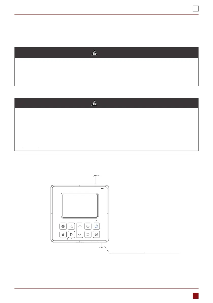
1.1 An overview of the wall-mounted remote control wire outlet
Top side wire outlet
Bottom side wire outlet
Fig. 1
1.2 Wiring diagram
Refer to the following diagram to wire the wall-mounted remote control to the indoor unit.
WARNING
• The wiring should adapt to the wire control current. Otherwise, electric leakage or overheating may
occur and result in re.
• The specied cables shall be used in the wiring. No external force may be applied to the terminal.
Otherwise, the wire may be damaged and heating may occur and result in re.
WARNING
• The shielded wire must be grounded .
• The connecting cable should not be longer than 20m (65.5’) .
• The remote control operates on a low voltage circuit loops. DO NOT connect a 220V or 380V cable
to the circuit loop.
• Make sure that congured tubes are 30-50cm (12-20”) or more apart.
• DO NOT employ an ohmmeter to detect the insulation after wiring the remote control.
PART 6. ZATO WIRED CONTROLLER SUPPORT
 Loading...