4 x Set-up and installation
FA ROTEX SC / SCS / HYC - 02/2013
19
Modifications on the electrical installation are dangerous and
prohibited. The operator alone shall bear responsibility for any
resulting damage.
Requirements
– For electrical connections and consumable electrical materi-
als (cable, insulation, etc.), follow all valid country-specific
guidelines.
– Cabling may only be connected to the terminal block intended
for this. No other terminal blocks may be used.
– Be sure that there is sufficient tension relief on all electrical
lines ( see chapter 8.3).
– The distance between the cabling of temperature sensors
and the power cable must always be at least 25 mm so that
the cables to the temperature sensor are not exposed to elec-
tromagnetic interference.
EHS/500/1
The EHS/500/1 is delivered ready to connect.
1. Check the power supply voltage of the mains connection
(~230 V, 50 Hz).
2. Insert the mains plug of the electric immersion heater into the
plug socket.
EHS/500/5, EHS/500/6
1. Check the power supply voltage of the mains connection
(~230 or 400 V, 50 Hz).
2. Disconnect the junction box of the domestic installation.
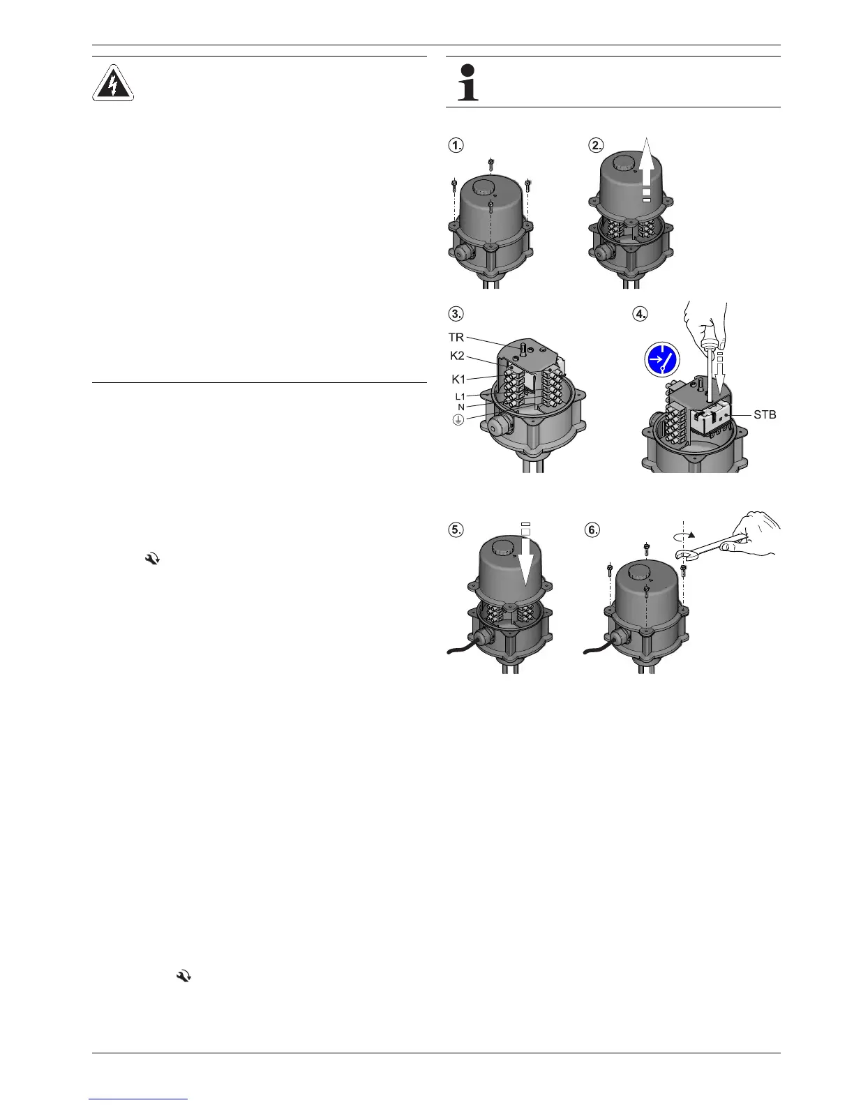
3. Unscrew the cap screws on the electric immersion heater and
remove the cap together with the regulating knob (fig. 4-10).
4. Remove and dispose of the folding sheet for installation.
5. Check the setting of the safety temperature limiter (STL)
(fig. 4-10); if necessary, push the pin in to release the
interlock.
6. Connect the electrical cables to the mains connection and the
terminal rail K1 on the electric immersion heater (fig. 4-10)
and connect to the mains connection of the domestic
installation ( see chapter 8.3).
– EHS/500/5 + EHS/500/6: fig. 4-11 or fig. 4-12
Ensure that the polarity is correct.
WARNING!
Touching live parts can result in an electric shock
and lead to potentially fatal injuries and burns.
Ɣ Before beginning work on live parts,
disconnect them from the power supply (switch
off fuse, main switch) and secure against uninten-
tional restart.
Ɣ The electrical connection and working on the
electrical components should only be performed
by electrical engineers in compliance with valid
standards and guidelines as well as the specifica-
tions of the energy supply company.
Ɣ For each rigidly fixed cable connection fit a
separate isolator in accordance with EN 60335-1
for all-pole disconnection from the power mains
and a residual current device RCD (FI) in
accordance with the individual country-specific
regulations.
Ɣ The equipment covers and maintenance
opening covers must be re-fitted immediately
after completion of the work.
As-delivered condition is "Connection variant l". For
Connection variants II + III the wiring on terminal block
K2 and the bridge positions must be adapted to suit.
K1 Terminal block (external connections)
K2 Terminal block (internal connections)
STL Safety temperature limiter
TR Temperature regulator (just EHS/500/5 and EHS/500/6)
Fig. 4-10 Electric immersion heater regulator unit
 Loading...