Do you have a question about the rotork YT-1200 Series and is the answer not in the manual?
Provides general information about the product for users.
Details the warranty terms and conditions for Rotork YTC Limited products.
Warns about explosion risks with external explosion-proof products, not the positioner itself.
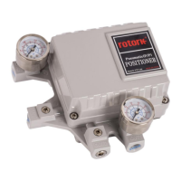
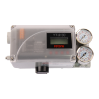
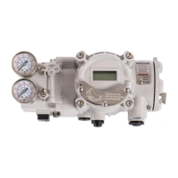
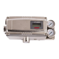
Overview of the YT-1200 series pneumatic positioner's function.
Lists key features and operational capabilities of the positioner.
Explains the information presented on the product's sticker labels.
Describes the structure and meaning of the YT-1200 product code.
Details technical specifications for the YT-1200 positioner.
Specifies technical details for SPTM-5V and SPTM-6V options.
Specifies technical details for YT-850 and YT-870 external limit switch options.
Exploded view and parts list for the YT-1200L model.
Exploded view and parts list for the YT-1000R model.
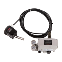
Assembly diagram for YT-1200R with external SPTM-6V.
Assembly diagram for YT-1000R with external YT-870.
Dimensional drawings for the YT-1200L model.
Dimensional drawings for the YT-1200R (Fork Lever type).
Dimensional drawings for the YT-1200R (Namur type).
Dimensional drawings for the YT-1200R (Dome indicator).
Dimensional drawings for the YT-1200R with external SPTM-6V.
Dimensional drawings for the YT-1000R with external YT-870.
Explains the operational principle of the linear positioner.
Explains the operational principle of the rotary positioner.
Safety precautions to be followed during positioner installation.
Lists the necessary tools required for installation.
Step-by-step guide for installing the linear positioner.
Lists the components required for rotary positioner installation.
Provides details and diagrams for rotary bracket assembly and adjustment.
Outlines the sequential steps for installing the rotary positioner.
Safety guidelines for air connection and supply.
Specifies requirements for clean, dry, and correctly pressured air supply.
Details requirements for proper air piping to ensure optimal flow.
Instructions for piping the positioner to a single acting actuator.
Instructions for piping the positioner to a double acting actuator.
Instructions for setting Direct Acting (DA) or Reverse Acting (RA).
Maintenance procedures for the pilot valve and its components.
Recommendation to check and replace seals annually.
Steps to diagnose and resolve issues with no response to input signals.
Troubleshooting guide for stuck Out1 pressure.
Diagnosing issues where pressure is only exhausted via the A/M switch.
Steps to identify and fix hunting problems in the positioner.
Troubleshooting for actuators moving only to extreme positions.
Steps to improve low linearity issues.
Steps to address and reduce hysteresis.
| Type | Electro-Pneumatic |
|---|---|
| Supply Pressure | 1.4 to 7 bar (20 to 100 psi) |
| Air Connection | 1/4" NPT |
| Protection | IP66 |
| Input Signal | 4-20 mA |
| Accuracy | ±0.5% of span |
| Material | Aluminum |
| Output Pressure | 0 to supply pressure |
| Mounting | NAMUR |
| Hazardous Area Certification | ATEX, IECEx |