Do you have a question about the rotork YT-3300 Series and is the answer not in the manual?
Provides essential information for users regarding product installation and safety.
Details the warranty terms and conditions, exclusions, and claims process.
Crucial safety information for intrinsic safety installations, covering installation requirements and potential hazards.
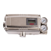
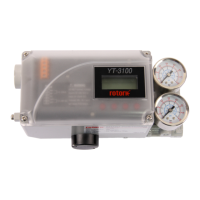
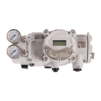
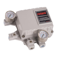
Overview of the Smart Valve Positioner series, its function, and core capabilities.
Lists key features like LCD display, fast boot-time, and operational stability.
Explains the meaning of various labels and codes found on the product for identification.
Details the coding system and options for YT-3300/3350 series product models.
Explains the product code structure and options specific to the YT-3303 series.
Describes the product code system and available options for YT-3301 and YT-3302 series.
Provides detailed technical specifications for YT-3300, 3303, and 3350 models.
Lists comprehensive technical specifications for the YT-3301 and YT-3302 models.
Details KCs, ATEX, and IECEx certifications, including intrinsic safety ratings.
Details FM, CSA, and INMETRO certifications, including safety and temperature ratings.
Information on SIL2 certification for safety functions and EMC compliance.
Exploded view and list of parts for YT-3300 and YT-3350 models.
Exploded view and identification of parts for the YT-3303 model.
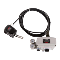
Exploded view of the YT-3301, showing positioner and remote sensor components.
Exploded view of the YT-3302, detailing positioner and remote sensor parts.
Dimensional drawings and measurements for various YT-3300 configurations.
Dimensional views and measurements for different YT-3350 models.
Provides detailed dimension drawings for YT-3303 linear and rotary models.
Dimensional drawings for YT-3301 and YT-3302 remote sensors and positioner main bodies.
Essential safety instructions and precautions to follow before and during positioner installation.
Lists the necessary tools required for the proper installation of the positioner.
Step-by-step guide for installing the linear positioner with a standard lever type.
Safety considerations for bracket design and positioning during standard lever type installation.
Detailed steps for assembling and attaching the positioner to the actuator yoke.
Guide for installing the adapter lever type on tubeless actuators.
Safety precautions related to feedback lever orientation and stroke length alignment for adapter lever installation.
Step-by-step instructions for installing the adapter lever type positioner.
General steps and components needed for rotary positioner installation.
Lists components and hardware required for installing YT-3300R/3350R rotary positioners.
Details the components and hardware needed for YT-3303R rotary positioner installation.
Lists components for installing YT-3301R/3302R rotary remote sensors.
Information on rotary bracket sets and how to adjust them based on actuator stem height.
Step-by-step guide for installing rotary positioners, including bracket adjustment and fork lever mounting.
Safety precautions for air connection, including supply pressure and exhaust venting.
Specifies requirements for supply air quality, filtration, and pressure levels.
Guidelines for clean, undamaged piping with appropriate diameter and length for air supply.
Illustrates and explains air piping connections for actuators.
Diagram and instructions for piping the positioner to a single acting actuator.
Illustrates and explains the air piping connection for double acting actuators.
Critical safety instructions for power connection, grounding, and cable management.
Overview of standard terminal connections for power and signal input/output.
Wiring details for connecting micro-limit switches to the positioner.
Instructions for connecting inductive proximity limit switches to the positioner.
Wiring diagram for connecting the main body to the remote sensor for YT-3301/3302.
Instructions for proper grounding of the positioner before operation.
How to adjust mechanical and inductive proximity limit switches on YT-3300/3350.
Procedures for adjusting the Auto/Manual (A/M) switch for bypass or positioner control.
Instructions for installing and adjusting orifices to control flow rate and prevent hunting.
Steps for installing optional sub-PCBs (HART, PTM) onto the main PCB.
Checks for proper supply air quality and pressure to ensure positioner functionality.
Recommendation to check and replace damaged rubber parts like diaphragms and o-rings annually.
Warning about separating the valve during auto-calibration to avoid affecting other processes.
Explains the LCD display symbols and the functions of the control buttons.
Overview of the menu structure, including Run Mode Monitor and Configuration/Operation.
Explains how to use the RUN Mode Monitor to view process variables and status.
Details the menus, submenus, parameter ranges, and factory settings.
Details calibration menus including Acting Type and Auto Calibration steps.
How to set the acting type (single/double) based on the actuator.
Procedure for performing Auto Calibration 1 to set zero and end points.
Guide for Auto Calibration 2, which tunes all parameters for valve operation.
Procedure for Auto Calibration 3, used for changing valve characteristics or due to aging.
Manual adjustment of valve zero and end points after auto calibration.
Guides on manually operating the valve via set position or manipulator value.
How to manually adjust the valve position using set position values.
Manually control the valve stem by adjusting the I/P converter input value.
Details on adjustable control parameters like Dead Band, PID, GAP.
Adjusting deadband to prevent limit cycle caused by valve friction.
Explains proportional gain parameters for valve response and stability.
Details integral time parameters for error correction and response speed.
Explains differential parameters for error rate correction and linearity.
Sets the control range for Gap control, interacting with PID parameters.
Function to suppress hunting in valves with high static friction.
Selects operating modes (Stable, Normal, Fast) for responsiveness.
Configuration settings for input signal direction and split range.
Sets the signal direction (NORM/REVS) affecting valve action type.
Sets input signal ranges (4-20mA, 4-12mA, 12-20mA, Custom) for valve stroke.
Sets the zero point current for custom split ranges.
Sets the endpoint current for custom split ranges.
Selects valve flow characteristics (Linear, QO, EQ, U5, U21).
Allows setting 5 custom points for valve characterization at 4mA intervals.
Enables setting 21 custom points for valve characterization at 0.8mA intervals.
Ensures the valve is fully opened with high force when input signal exceeds set value.
Ensures the valve is fully closed with high force when input signal drops below set value.
Controls valve movement speed to prevent over-sensitivity to process changes.
Settings for position transmitter direction and HART feedback.
Sets the direction of the analog feedback signal relative to actual valve position.
Adjusts the zero (4mA) and end (20mA) points of the position transmitter feedback.
Configures HART feedback signal direction relative to actual valve position.
Recalculates output value for linear display relative to actual input current.
Configuration settings for action, lever type, interpolation, and parameter lock.
Sets the action type (Reverse/Direct) for the positioner.
Selects between standard or adapter type for the linear lever.
Compensates linear motion to rotary motion for feedback lever angle.
Enables or disables parameter locking to prevent unauthorized changes.
Sets how the RUN AP value is displayed (direct or reversed) relative to valve position.
Sets the address value for HART communication.
Initializes all stored parameters to factory default settings.
Diagnoses the operation of internal memory (RAM/NVM) for errors.
Accesses diagnostic functions like alarm settings, status, and logs.
Sets initial factory values for handling alarms and status conditions.
Displays current process status using GOOd, NE107 symbols, or alarm abbreviations.
Indicates the current device status using GOOd, NE107 symbols, or alarm abbreviations.
Displays accumulated data for valve movement history.
Sets upper/lower limits for Travel High/Low Limit alarms.
Releases alarms manually after the cause is removed.
Shows the 20 most recent operational events with time and content.
Displays records of the last 10 Partial Stroke Tests performed.
Configures parameters for Partial Stroke Test execution.
Initiates a Partial Stroke Test immediately based on configured conditions.
Schedules regular execution of Partial Stroke Tests.
Accesses detailed information about the positioner's status and settings.
Lists error codes and causes during automatic calibration with suggested actions.
| Type | Electro-Pneumatic |
|---|---|
| Input Signal | 4-20 mA DC |
| Linearity | ±1% F.S. |
| Repeatability | ±0.5% F.S. |
| Connection | 1/4" NPT |
| Supply Pressure | 1.4 - 7 bar |
| Material | Aluminum |
| Protection Class | IP66 |
| Hazardous Area Certification | ATEX, IECEx |
| Mounting | NAMUR |
| Housing Material | Aluminum |