Do you have a question about the rotork YT-2500 Series and is the answer not in the manual?
General information and thank you note for purchasing Rotork YTC Limited products.
Details warranty terms, exclusions, and responsibilities for product safety.
Warning for intrinsic safety types regarding installation and safe use in hazardous areas.
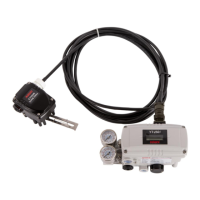
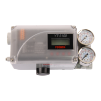
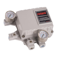
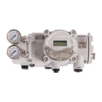
Overview of the Smart Valve Positioner's function in controlling valve stroke with an input signal.
Lists key features like input signal failure handling, LCD display, and ease of use.
Explains the meaning of various labels and markings on the product's nameplate.
Details how to interpret the product code structure for YT-2500/2550 and YT-2501 series.
Provides detailed technical specifications for YT-2500/2550 and YT-2501 models.
Lists various certifications (KCs, ATEX, IECEx, NEPSI, TRCU, CCC, EMC) for the product.
Essential safety instructions to follow before and during positioner installation.
Lists necessary tools required for the installation process.
Guides on installing linear positioners on linear motion valves.
Instructions for installing rotary positioners on rotary motion valves.
Safety precautions related to air supply, emphasizing clean and dry air.
Specifies requirements for dry air, dew point, filter micron rating, and pressure range.
Guidelines for piping installation, including ensuring cleanliness and proper diameter.
Details pneumatic connections for single-acting and double-acting actuators.
Critical safety warnings regarding power connections, terminal types, and grounding.
Illustrates the terminal overview and wiring for input signal and feedback.
Instructions for proper grounding of the positioner before operation.
How to adjust the sensing position of limit switches for mechanical and inductive types.
Procedure for adjusting the variable orifice to prevent hunting and optimize flow.
Step-by-step guide for installing optional sub-PCBs like HART or Limit Switch.
Importance of stable and clean supply air for proper positioner function.
Recommendation for annual inspection and replacement of damaged rubber parts like diaphragms.
Warning about the automated process operating the valve and actuator during calibration.
Identifies the four buttons and their basic functions for navigation and operation.
Describes RUN mode display messages and how to navigate through them.
Explains the auto-calibration process and its three types (AUTO1, AUTO2, AUTO3).
Adjusts zero and end points, recommended after valve manufacturer setup.
Adjusts all parameters, recommended for initial installation or reassembly.
Adjusts parameters except zero and end points.
Allows manual control of the valve stem using the UP/DOWN buttons.
Overview of parameter adjustment for tuning and preventing hunting/oscillation.
Percentage of error allowance; adjust to stabilize valve operation.
Ratio of compensation signal; affects speed and stability of target point finding.
Derivative value of compensation signal; affects hunting and linearity.
Principles same as P1/D1, applicable when input signal is decreasing.
Principles same as P/D, activated when error reaches within 1%.
Minimum time duration for internal signal controlling pilot valve.
Automatically creates deadzone after calibration to stabilize valve operation.
Used for re-adjusting zero and end points after auto-calibration.
Adjusts the zero and end points of the valve.
Adjusts transmitter's zero/end points for unstable output.
Changes the positioner's feedback signal to normal or reverse.
Changes HART communication feedback signal to normal or reverse.
Offers various function settings for control valve operation.
Changes Direct Action (DA) or Reverse Action (RA) settings.
Sets valve flow characteristics like Linear, Quick Open, EQ%, or User Set.
Allows creation of custom flow characteristic curves using 5 or 18 points.
Sets percentage for immediate valve movement to 100% on input signal increase.
Sets percentage for immediate valve movement to 0% on input signal decrease.
Enables operation via split range control (4-12mA or 12-20mA).
Displays various information about the positioner, such as version and operational status.
Lists error codes encountered during auto calibration and their causes/actions.
Describes error codes that appear during normal product operation.
Explains how to check error codes via the View mode and their meanings.
Lists warning codes viewable in View mode and their corresponding actions.
| Action | Single or Double Acting |
|---|---|
| Supply Pressure | 1.4 ~ 7 kgf/cm² (20 ~ 100 psi) |
| Ambient Temperature | -20 ~ 80°C (-4 ~ 176°F) |
| Material | Aluminum |
| Protection | IP66 |
| Enclosure Rating | NEMA 4X |
| Housing Material | Aluminum |