Do you have a question about the rotork YT-3750 and is the answer not in the manual?
Provides crucial warnings and guidelines for using the product in potentially explosive environments.
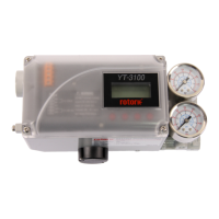
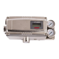
Lists the technical specifications for the YT-3700 and YT-3750 positioner models.
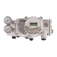
Details the technical specifications for the YT-3702 positioner model.
Outlines critical safety instructions to follow during positioner installation.
Details the procedure for installing linear type positioners.
Highlights safety precautions specific to linear positioner installation.
Provides step-by-step instructions for installing standard lever type positioners.
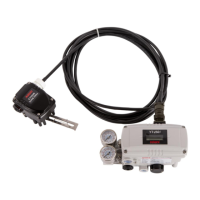
Explains how to install rotary type positioners.
Details the step-by-step installation process for rotary positioners.
Outlines safety precautions related to air connections for the positioner.
Explains air piping connections for single acting actuators.
Lists safety precautions for power connections to the positioner.
Explains the adjustment procedure for the Auto/Manual (A/M) switch.
Alerts users about potential valve movement during auto-calibration.
Details menus for configuration, calibration, and operation of the positioner.
Provides the calibration menus including acting type and auto calibration.
Describes AUTO 1 calibration for setting origin and end points.
Explains AUTO 2 calibration for tuning all operation parameters.
Details the Dead Band parameter for controlling valve deviation.
Explains proportional gain parameters for controlling valve response.
Details integral time parameters for correcting valve response errors.
Explains differential gain parameters for valve control.
Describes how to perform a factory reset of the positioner parameters.
Explains how to run a self-test to diagnose positioner memory operation.
Shows factory default alarm settings and NE107 signal assignments.
Explains how to manually reset specific alarms.
Explains how to view results of recent Partial Stroke Tests.
Details the configuration parameters for Partial Stroke Tests.
Explains how to perform a Partial Stroke Test immediately.
Describes how to schedule periodic Partial Stroke Tests.
Lists and explains error codes encountered during automatic calibration.
Provides a table of status and alarm codes with descriptions and proposed actions.
Provides installation drawings related to FM certification for intrinsic safety.
Provides installation drawings related to CSA certification for intrinsic safety.
| Brand | rotork |
|---|---|
| Model | YT-3750 |
| Category | Valve Positioners |
| Language | English |