ROYAL ENFIELD WORKSHOP MANUAL
13. Spokes
The spokes are of the single butted type 8-10
gauge with 90° countersunk heads, angle of
bend 95°-100°, length 6.5/8 in. brake drum side,
8.1/2 in. spoke flange side, thread diameter .144
in., 40 threads per inch, thread form British
Standard Cycle.
14. Wheel Building and Truing
The spokes are laced one over two on the
brake side and one over three on the spoke flange
side of the wheel. The wheel must be built
central in relation to the faces of the nuts on the
spindle. The rim should be trued as accurately as
possible, the maximum permissible run-out both
sideways and radially being plus or minus 1/32
in.
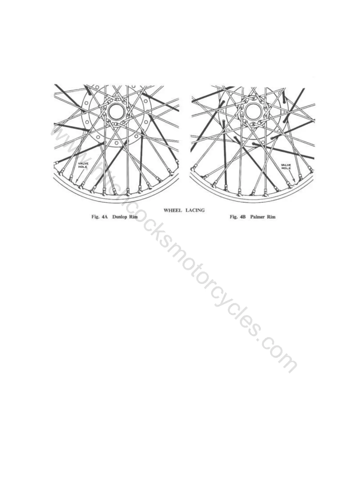
Figs. 4A and 4B show the difference between
the lacing when using Dunlop and Palmer rims.
The key to correct lacing is the inside spokes to
the large flange on the brake drum side which
must slope in the direction shown in Fig. 4. With
the Dunlop rim this spoke goes to the middle
hole of one of the groups of three (see
Subsection 12) and the rim must be built into the
wheel so that these groups of three holes are on
the right of the centre line when the brake drum
is on the left, i.e. the inside spokes to the large
flange cross from the left to the right of the
centre line.
With the Palmer rim the spokes from the large
flange on the brake drum side go to the more
steeply angled holes in the rim which must be on
the left of the centre line when the brake drum is
on the left, i.e. none of the spokes crosses from
left to right of the centre line.
15. Tyres
Standard tyres on the "250 Clipper" and
"Model S" are Dunlop 3.00-19 in. Lightweight
Reinforced and on the other models Dunlop
3.25-19 in. Ribbed.
When removing the tyre always start close to
the valve and see that the edge of the cover at the
other side of the wheel is pushed down into the
well in the rim.
When replacing the tyre fit the part by the
valve last, also with the edge of the cover at the
other side of the wheel pushed down into the well.
If the correct method of fitting and removal of
the tyre is adopted it will be found that the tyres
can be manipulated quite easily with the small
levers supplied in the toolkit. The use of long
levers and/or excessive force is liable to damage
the walls of the tyre. After inflation make sure that
the tyre is fitting evenly all the way round the rim.
A line moulded on the wall of the tyre indicates
whether or not the tyre is correctly fitted. If the
tyre has a white mark, indicating a balance point,
this should be fitted near the valve.
Section K2 Page 4
www.hitchcocksmotorcycles.com
 Loading...