EP Series User Manual
5
2. Hardware connection
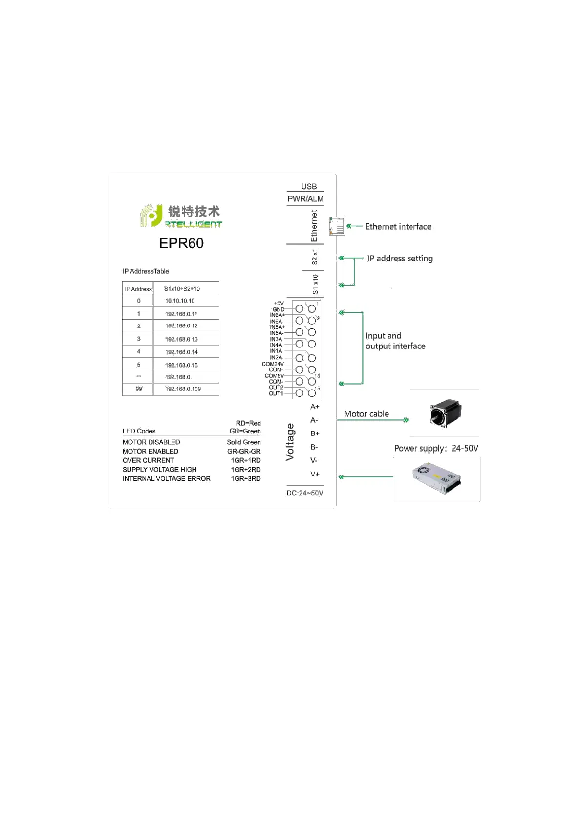
2.1. Hardware connection diagram
The following sections provide a detailed description of the hardware and how to
use it. The hardware diagram is as follows:
Figure 2-1 Hardware diagram
2.2. Power supply connection
Connect the driver to DC power supply: V+ is connected to the positive of the
DC power supply, V- is connected to the negative of the DC power supply.
The maximum input voltage of the EPR60/EPT60 is 18~50VDC, do not exceed
this specification.
If your power output does not have a fuse or other device that limits the
short-circuit current, you can place an appropriately sized fast-blow fuse (no
more than 10Amps) between the power supply and the driver to protect the
driver and the power supply, please connect this fuse in series between the
 Loading...