EP Series User Manual
7
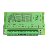
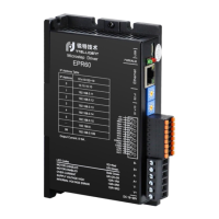
2.4. Digital input and output interface
The EP series driver has 6 digital input ports and 2 digital output ports. The digital
input and output ports can be freely configured with various functions according to their
own application requirements.
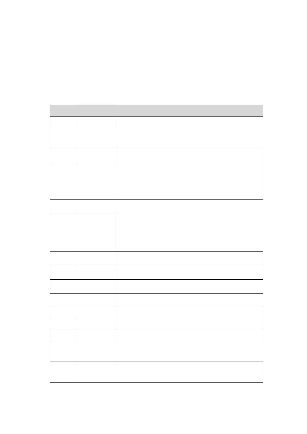
2.4.1. Pin definition
Table 2-1 Pin definition of CN
The driver outputs a 5V power supply for external
signals.Maximum load: 150mA.
It can be used for power supply of optical encoder.
Differential input signal interface, 5V~24V compatible.
In open-loop external pulse mode, it can receive direction.
In closed-loop mode, this port is used to receive quadrature
encoder A-phase signal.
Note:The closed-loop mode is only applicable to the EPT60.
Differential input signal interface, 5V~24V compatible.
In open-loop external pulse mode, it can receive direction.
In closed-loop mode, this port is used to receive quadrature
encoder B-phase signal.
Note:The closed-loop mode is only applicable to the EPT60.
Universal input port 3, default to receive 24V/0V level signal.
Universal input port 4, default to receive 24V/0V level signal.
Universal input port 1, default to receive 24V/0V level signal.
Universal input port 2, default to receive 24V/0V level signal.
External IO signal power supply 24V positive.
Internal power supply output GND.
External IO signal power supply 5V positive.
Output port 2, open collector, output current capability up to
100mA.
Output port 1, open collector, output current capability up to
30mA.
 Loading...