Do you have a question about the Rtelligent EP Series and is the answer not in the manual?
Overview of the EP series stepper motor driver and its features.
Details the key technical specifications and capabilities of the EP series driver.
Lists the electrical specifications and parameters of the EP series driver.
Outlines critical safety precautions for handling, installation, and operation.
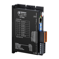
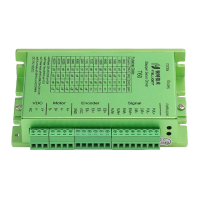
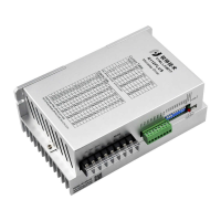
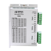
Illustrates the physical connections and components of the EP series driver.
Details how to correctly connect the DC power supply to the driver.
Explains how to connect the stepper motor to the driver, including wire colors.
Defines the function and pinout of the digital input/output interface connectors.
Details the pinout and function of each connector on the driver.
Describes the schematic and configuration of the driver's digital input ports.
Details the digital output signals and their capabilities.
Covers the steps for connecting the driver to a network and configuring IP settings.
Instructions for downloading and installing the RTConfigurator software.
Guides on establishing an Ethernet connection between the driver and a computer.
Explains the IP address configuration format and factory defaults for the driver.
Lists various alarm codes and their corresponding driver status indications.
Provides physical dimensions and mounting information for the driver.
Introduces the Modbus/TCP communication protocol and its application.
A summary table of Modbus registers for the EP series driver.
Details the bits and meanings of the driver flag registers for alarms.
Provides status information for the driver's input and output ports.
Registers related to motor position and speed tracking.
Settings for various driver control modes.
Parameters for configuring open-loop motor operation.
Parameters for motor and current loop control.
Parameters for closed-loop motor control.
Parameters specific to closed-loop servo operation.
Registers for configuring input and output port functions.
Parameters for point-to-point motion control.
Parameters for jog speed mode operation.
Parameters for internal pulse control.
Basic parameter registers for the driver.
Settings for speed table control.
Settings for position table control.
Parameters for multi-segment position running control.
Settings for homing control modes.
Controls motor movement via communication commands.
Details setting up point-to-point motion control using communication.
Describes how to control motor jog operation via communication.
Utilizes two IN ports for motor start/stop and direction control.
Uses two IN ports for controlling forward and reverse motor operation.
Configures motor speeds using IO signals and a speed table.
Controls motor position using settings from a position table.
Explains the message format for Modbus function codes.
Details the query and response message structure for reading holding registers.
Details the message structure for writing multiple Modbus registers.
| Brand | Rtelligent |
|---|---|
| Model | EP Series |
| Category | Control Unit |
| Language | English |