EP Series User Manual
60
(1) Set the value of register 20 to 0. Among them, register 20 indicates the preset
application program selection in internal pulse mode; P20=2 indicates Start-stop +
Direction mode.
(2) Set the functions of digital input and output ports according to application needs
and actual wiring terminals. Among them, please set the function of the two IN
terminals to "Jog forward/Start-stop" and “Jog reverse/Direction" to control the
start/stop and running direction of the motor. For the function setting of IN terminal,
please refer to "Input port setting register [60~65]".
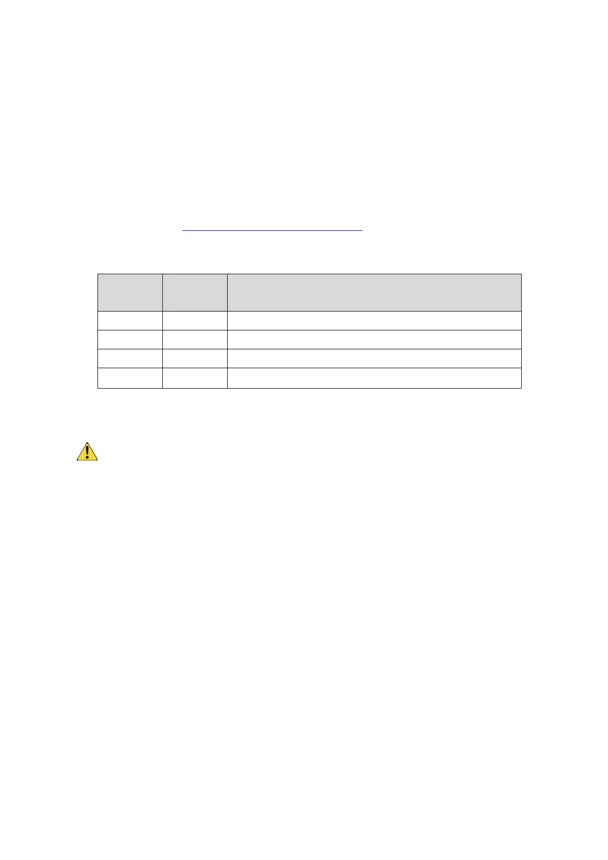
(3) Set motion parameters:
Table 4-3 Motion parameter settings in Start-stop + Direction mode
Emergency stop deceleration
(4) Input the appropriate level through the corresponding IN port to control the running
and direction of the motor.
Acceleration (register 75), deceleration (register 76), speed (register 77) and
emergency stop (register 78) can be dynamically changed during motor running,
and the driver will respond to these settings immediately.
The direction signal can be switched during the motor running. At this time, the
motor will decelerate and stop at the deceleration set by register 75, and then
accelerate to the set speed in the opposite direction.
4.3. IO control: Forward + Reverse
EP series drivers can use two IN ports to control the operation of the motor through
this mode. One of the IN terminals is used to control the forward of the motor, and one
of the IN terminals is used to control the reverse of the motor. The specific settings are
as follows:
(1) Set the value of register 20 to 0. Among them, register 20 indicates the preset
application program selection in internal pulse mode; P20=2 indicates Forward +
Reverse mode.
 Loading...