19
It’s Under Control
®
CHAPTER 3 | INSTALLATION AND OPERATION
The function of each pin on the I/O port is described below.
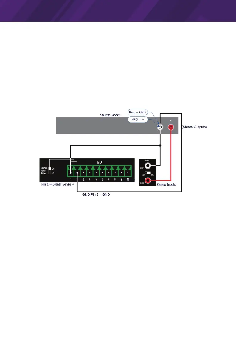
Pin 1 - Signal Sense
Pin 1 on the 10-pin I/O port is used for single-ended Signal Sense input (+).
This pin detects an input signal from a source device when the source device
is active. Pin 1 (Signal Sense +) connects to one of the source device’s input
cables to provide a signal to the CP-16i when the source device is active.
Pin 2 - Signal Sense Input Ground
Pin 2 on the 10-pin I/O port is used for Signal Sense input ground (-).
PIN 1 Example - Signal Sense Connection (Unbalanced)
External Signal Sense Switch
With the External Signal Sense switch in the ON position, the amplier is
automatically turned on when an audio signal is present, and automatically
placed in standby mode when no audio signal has been present on the signal
terminals for approximately 13 minutes.
• Note that the example diagram indicates the Signal Sense connection tied
to the Left output from the source device, but Signal Sense can come from
either output.
• The amplier will power up if a signal is applied to the signal sense input.
By default, the External Signal Switch is set to the ON position.
Pin 3 - 12V (In) Trigger
The CP-16i can be turned On or placed in Standby mode externally via a 12V
Trigger signal. A 12V trigger input is accessible via Pin 3 on the 10-pin I/O port.
 Loading...