Cool Power
®
Audio Amplier
CP-16i
20
CHAPTER 3 | INSTALLATION AND OPERATION
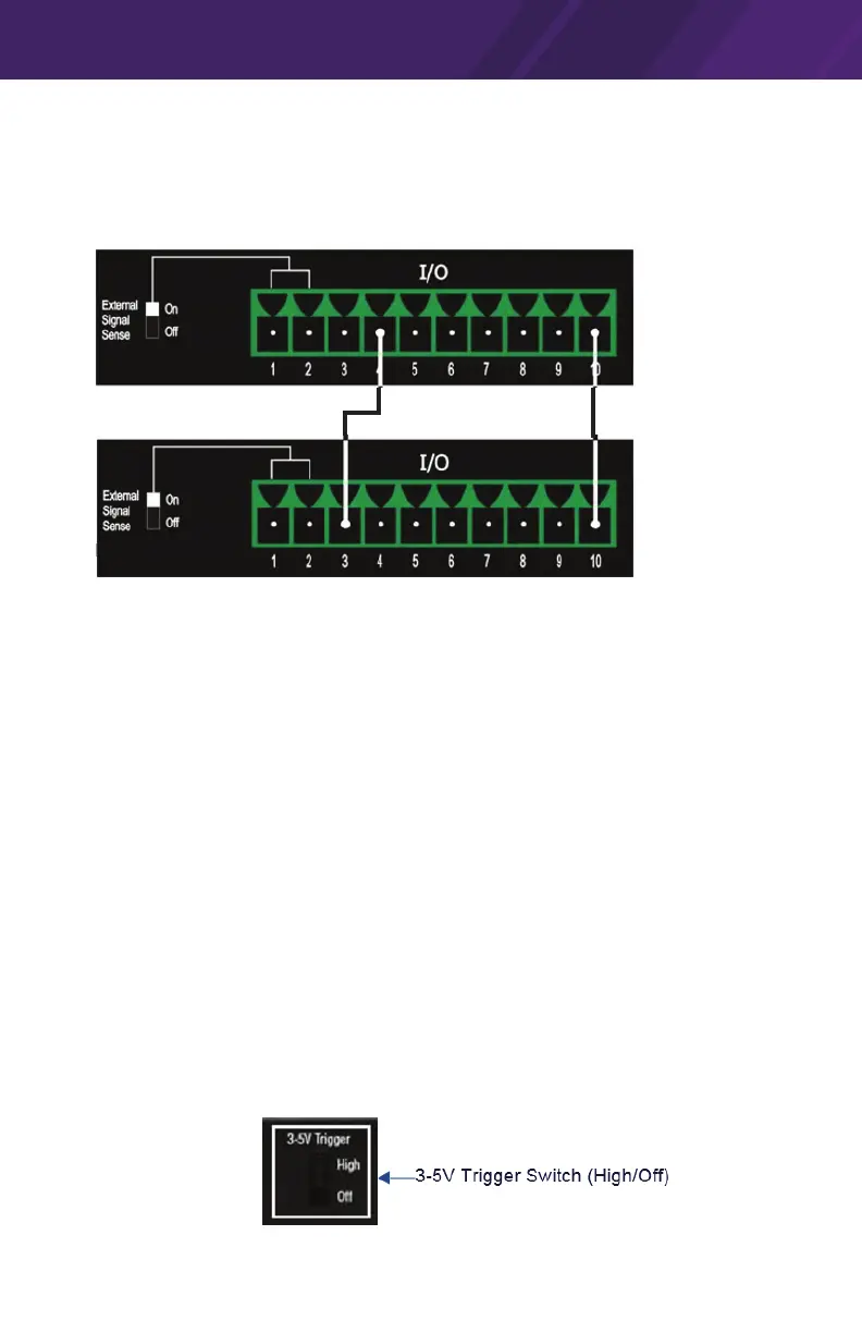
Pin 4 - Trigger (Loop Out)
The CP-16i also provides a convenient way to daisy-chain a 12V trigger to other
devices. Any voltage provided to Pin 3 is looped out to Pin 4 of the 10-pin I/O
port:
Pin 4 = 12V Trigger (Out)
I/O port on
rst amplier
Pin 10 = Status GND
I/O port on
downstream
Pin 3 = 12V Trigger In
Pin 10 = Status GND
PIN 4 Example - Trigger (Loop Out) Connections
Pin 4 connects to a +12V Trigger (input) on a downstream amplier
NOTE: Pin 3 and Pin 4 are hard wired together. Therefore, when a trigger is
applied to pin 3 it will also be present at pin 4. Pin 4 will be high only if a signal
is applied to Pin 3.
Pin 5 - Local/Trigger GND
Pin 5 on the 10-pin I/O port provides a ground connection for the 3-5V Logic
Level Trigger. Pin 5 connects to the GND pin of an I/O port on an external
controller.
Pin 6 - 3-5V Logic Level Trigger
The CP-16i can be also turned On or placed in Standby mode externally via a
3-5V Logic Level trigger signal. A 3-5V trigger input is accessible via Pin 6 on
the 10-pin I/O port.
3-5V Trigger Switch
The 3-5V Trigger Switch has two selections; High and O.
When the 3-5V Trigger Switch is set to High, the amplier will turn on when AC
mains is turned on, For example, the 3-5V Trigger switch could be set to High
if the amplier needs to be forced on without having signal sense or external
trigger signals.
 Loading...