Do you have a question about the RTI Cool Power CP-16i and is the answer not in the manual?
Key operational guidelines and precautions for the CP-16i amplifier.
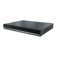
Details the items included in the CP-16i amplifier box.
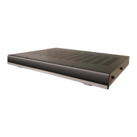
Description of the LEDs on the front panel and their meanings.
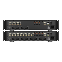
Diagram and explanation of rear panel connectors and controls.
Methods for powering the CP-16i on/off externally.
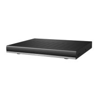
Guidance on securely mounting the CP-16i in a rack or on a surface.
Ensuring adequate airflow for the CP-16i unit for proper operation.
Safety considerations for installing equipment in a rack.
Instructions for connecting audio source devices and speaker wiring.
Pinout details for the audio input connectors on the rear panel.
Explanation of switches to set audio input to Stereo or Bridge mode.
How to connect stereo audio sources to the CP-16i inputs.
How to connect audio sources for bridged output.
Guidelines for connecting speakers using Class 2 wiring.
Pinout details for the speaker output terminals on the rear panel.
Detailed wiring for connecting stereo speakers to the CP-16i.
Table mapping audio inputs to speaker outputs in Stereo Mode.
Detailed wiring for connecting speakers in Bridge Mode.
Table mapping audio inputs to speaker outputs in Bridge Mode.
Description of the 10-pin I/O port for external control and status.
Pinout details for the 10-pin I/O control port.
Function of Pin 1 for detecting active source device signals.
Function of Pin 2 for Signal Sense input ground.
How the switch enables automatic power on/off based on audio signal.
Using Pin 3 for external 12V trigger control of power state.
Function of Pin 4 for looping out 12V trigger signals.
Pin 5 provides a ground connection for 3-5V Logic Level Trigger.
Using Pin 6 for external 3-5V logic level trigger control.
Setting the 3-5V trigger switch for amplifier turn-on behavior.
Output signals for thermal and overcurrent status to external controllers.
Pin 9 provides on signal output or acts as a 12V trigger output.
Pin 10 provides ground reference for output pins (7-9).
Summary of external control methods for power state.
How to enable or disable individual zones using the dip switch.
Pinout details for the AC power connector on the rear panel.
Steps to put the CP-16i amplifier into standby mode.
Physical dimensions, weight, and warranty information.
Detailed audio performance specifications like channels, power, THD.
Electrical specifications including mains power, fuse, and consumption.
Environmental operating temperature and thermal dissipation ratings.
How to contact Remote Technologies Incorporated for information and updates.
Information on obtaining technical support and required details.