2. Installation
RuggedCom® RuggedSwitch™ 13 RS900G Installation Guide Rev 107
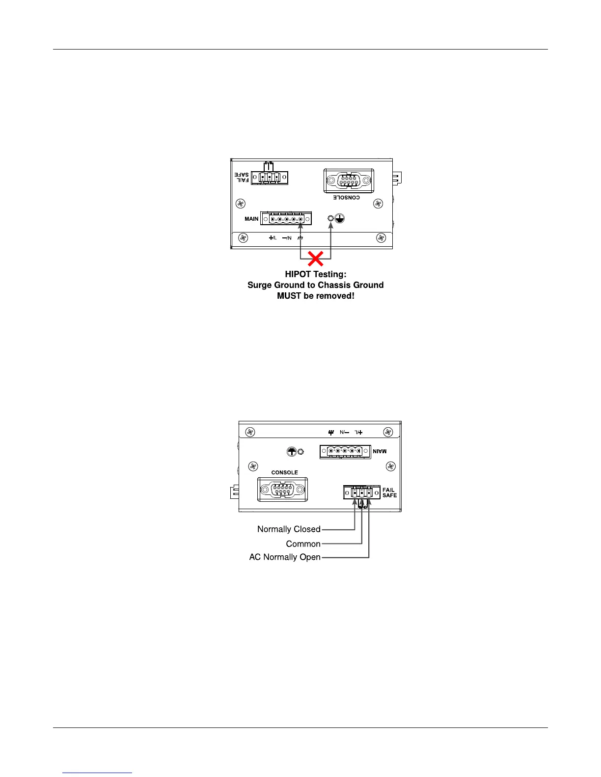
2.3. HIPOT (Dielectric Strength) Testing
Units which are to be “HIPOT” tested in the field must have the braided ground cable disconnected
(see Figure 2.4, “HIPOT (Dielectric Strength) Testing”) during the HIPOT test. This is required in
order to prevent the transient/surge suppression circuitry, which is connected to Surge Ground,
from being activated during the HIPOT test.
Figure 2.4. HIPOT (Dielectric Strength) Testing
2.4. Failsafe Output Wiring and Specifications
The “Failsafe” output relay is provided to signal critical error conditions that may occur on the
RS900G. The contacts are energized upon power up of the unit and remain energized until an
alarm condition or power loss occurs.
Figure 2.5. Failsafe Output Relay
2.5. RS232 Port Wiring
The RS232 port is used for configuring the unit. A straight-through serial cable with a DB-9
connector is required. There is no need to crossover the Transmit and Receive signals from the
PC side since this has been done internally as shown in the figure below.