36
COMPILER TECO/ATI ENDORSEDDATE
23.06.2003
REG. CODE
1-5302-602
MODEL N°
50884
DATE OF ISSUE
06-03
REVISION 00
77
78
79
80
XIII
1,75 ÷ 2,25 mm
4 kgm (Nm 39,2)
0,15 mm
ENGINE ASSEMBLY
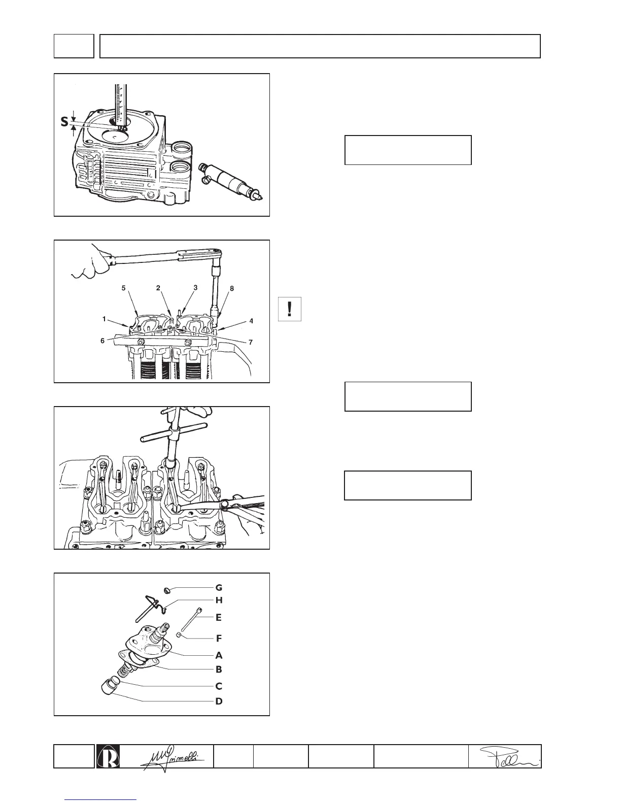
Checking injector protrusion
Before mounting the heads to the cylinders fit the injectors into their
housings and, after having secured them temporarily, check the
protrusion of the nozzles from the head faces (fig.77). Protrusion S
should be:
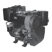
Cylinder heads
For checking and overhaul of the cylinder heads refer to page 19.
Fit the push rods and oil sealing O-rings on the cover pipes and
proceed to install the cylinder heads with the relative gaskets on the
facing surfaces.
Make sure that the oil seal rings are correctly seated in the
heads to avoid the risk of oil leaks.
Align the heads using a metal bar or the exhaust manifold (fig.78).
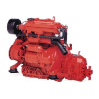
Following a cross pattern tighten the head nuts (fig.78) in
increments of 1 kgm until you reach the value:
This value is adjusted by inserting copper washers between the
injectors and the injector supporting faces on the heads (fig. 77).
Valve clearance
The clearance between valves and rockers with the engine cold
(fig.79) is:
This clearance is to be adjusted with the pistons at their respective
TDC compression positions.
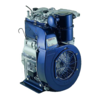
Injection pumps
1.Insert the injection pump tappet (D) and spacer (C) into the
housings in the crankcase (fig.80).
2.Assemble the injection pumps (A fig. 80) on the crankcase and
secure them on the adjustment sleeve by means of the
appropriate pins (E or H fig. 80) on PF30 BOSCH pumps. Then,
place the advance adjustment shims (B, fig. 80) between the
crankcase and the pump.
3.Fix the injection pump connection rod (A, fig.81) to the speed
governor lever tie rod (B, fig.81)
4.Secure the injection pumps to the crankcase, taking care to turn
the first injection pump around through approximately 3/4 of a
turn in a clockwise direction.
intake/exhaust