22
17-04-2003
01
15-01-2004
DATE
COMPILER TECO/ATI
REG. CODE
1-5302-584
MODEL N°
50871
DATE OF ISSUE
REVISION
ENDORSED
8
VIII
11
9 10
A
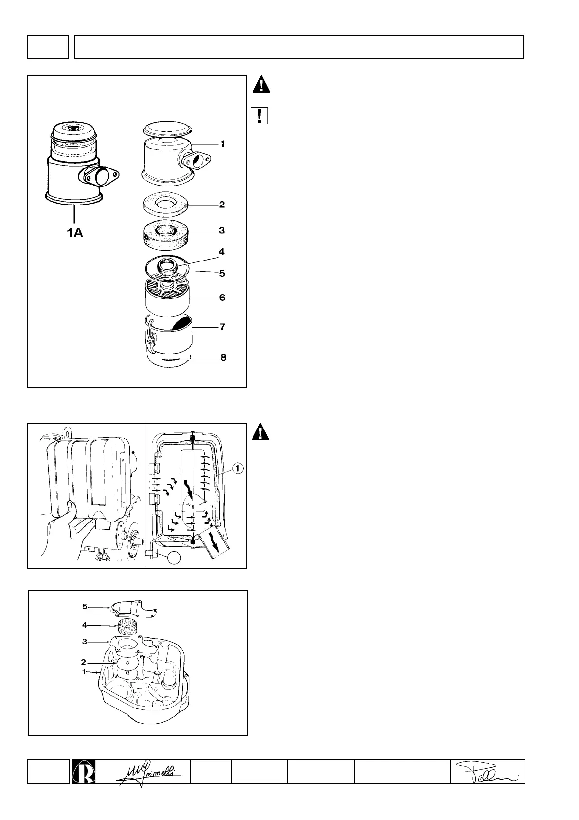
Never clean the filtering element 6 using solvents with a low
flash point. This could cause an explosion !
Make sure that the retention rings 4 - 5 are in a good
condition and replace them if they are damaged.
Oil-bath air cleaner (optional)
Components:
1 Upper shell
1A Upper unit with separator pre-filter
2 Secondary filter element
3 Primary polyurethane
4 Internal seal ring
5 External rubber gasket
6 Lower metal filter element
7 Lower cup
8 Oil level gauge
Characteristics of filter element 2:
made of Viledon synthetic fabric, porosity 120 gr/m
2
, resin-covered.
Characteristics of filter element 3:
open-celled polyurethane foam; porosity 45 P.P.I..
Both filter elements can be washed with soap and water for a maxi-
mum of 10 times.
Wash the metal filter 6 with Diesel fuel Blow out excess fuel with
compressed air. See pages 14 and 15 for periodic maintenance
details and oil replacement.
Allow the exhaust manifold to cool before demounting it in
order to prevent scorching and burns.
Muffler
When reassembling replace the exhaust manifold gaskets.
Tighten nuts to 25 Nm.
The muffler design includes internal sound absorbing panels.
Tighten the bearing nuts and screw A to a 25 Nm torque value.
Rocker arm cover breather system
The crankcase breather system is located inside the rocker arm
cover. Check that diaphragm 2 is intact ; wash with Diesel oil and
blow through the small mesh element 4 with compressed air.
When reassembling fix box 3 with Loctite " Form-a- gasket No. 6"
and screw plate 5. Also see below.
DISASSEMBLY/REASSEMBLY