53
17-04-2003
01
15-01-2004
DATE
COMPILER TECO/ATI
REG. CODE
1-5302-467
MODEL N°
50707
DATE OF ISSUE
REVISION
ENDORSED
X
101
102
103 104
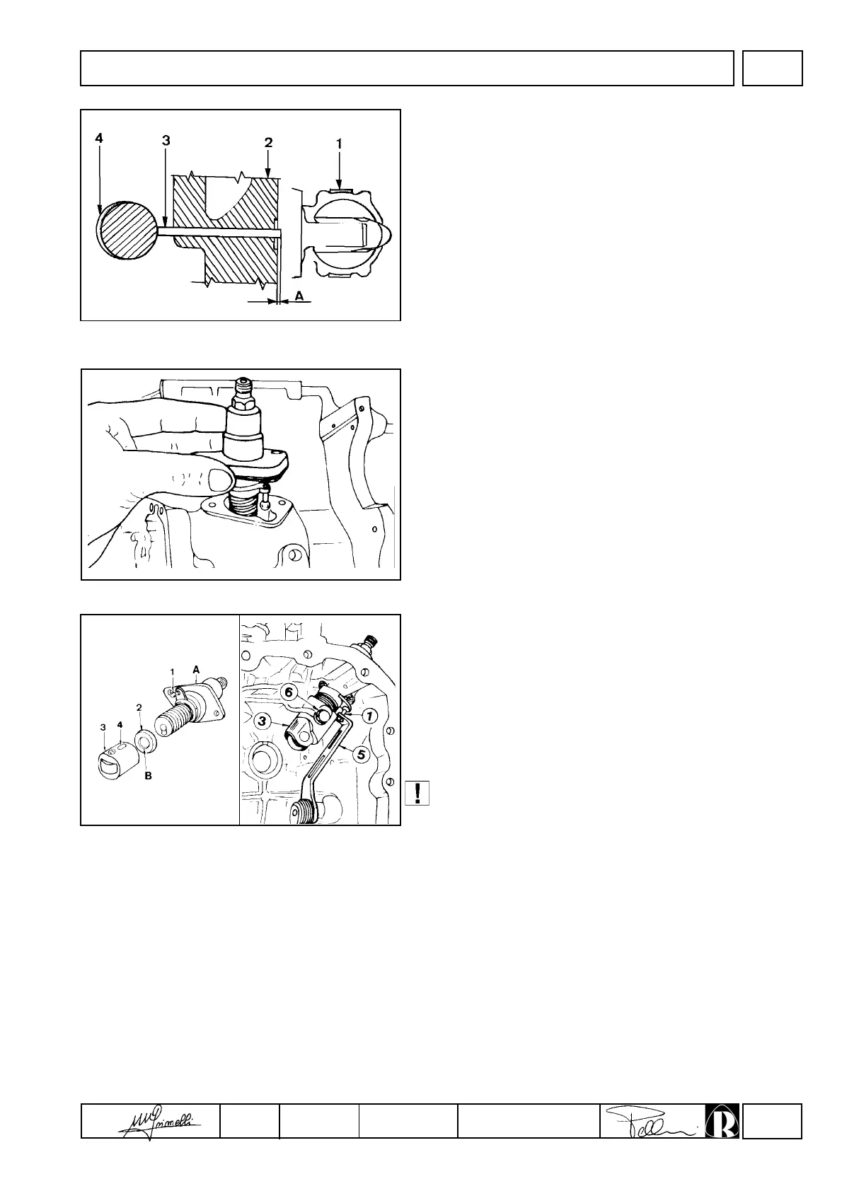
Fuel pump, drive rod protrusion
Components:
1 Fuel pump
2 Crankcase
3 Drive rod
4 Eccentric
Check while eccentric 4 is at rest (lowest point of travel).
Protrusion A of drive rod 3 is 1.5-1.9 mm; it is not adjustable.
Drive rod length = 58-58.2 mm for RY 50
Drive rod length = 65.8-66.0 mm for RY 70-75
Drive rod length = 61,4÷61,6 mm for RY 103-110
Injection pump
This is of the simplified QLC type; it is housed in the crankcase
and is controlled by the camshaft via tappets.
Injection pump fitting in the crankcase
Fit tappets 3 so that screw 6 is introduced into guide 4.
Tighten screw 6 to 9 Nm and check that the tappet is free to move
downwards.
Fit pad 2 into the tappet so that recess B points downwards as
shown in the figure.
Fit the injection pump into the crankcase complete with gasket (C)
position8ing flow control 1 in the fork of lever 5 which should be in
the maximum flow position.
When removing the injection pump from its housing make
sure that spacer 2 is not dropped into the oil sump;
injection pump operation will be impaired uf the spacer is
not installed.
FUEL SYSTEM