61
17-04-2003
01
15-01-2004
DATE
COMPILER TECO/ATI
REG. CODE
1-5302-467
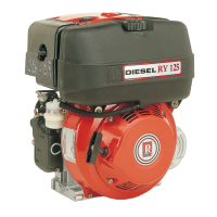
MODEL N°
50707
DATE OF ISSUE
REVISION
ENDORSED
XI
124
122
123
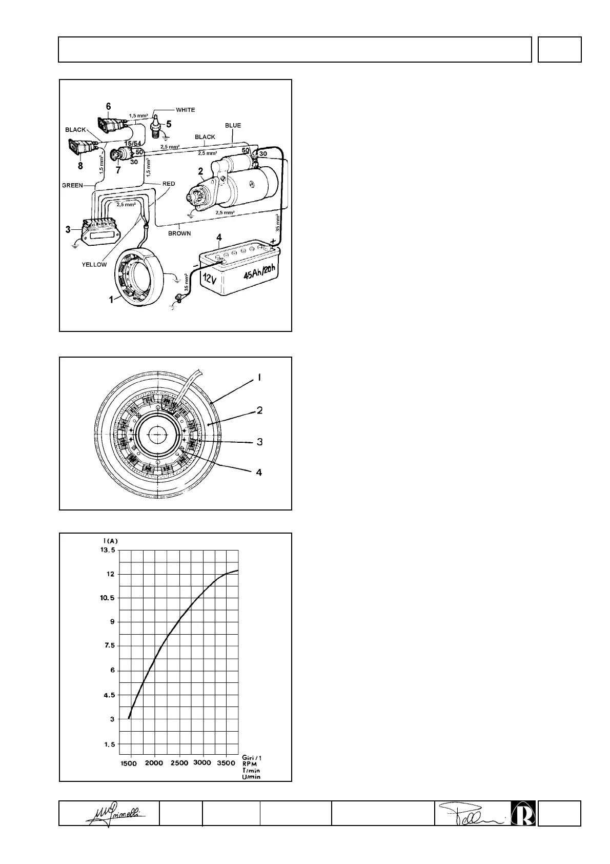
12V, 12A electric ignition diagram
Components:
1 Alternator
2 Starter motor
3 Voltage regulator
4 Battery
5 Pressure switch
6 Oil pressure light
7 Key switch
8 Battery charging light
Note: The battery, which is not supplied by RUGGERINI, should
have 12V nominal voltage rating and a capacity of not less
than 44 Ah / 210 Amp. of fast discharge intensity.
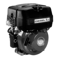
Alternator
Components:
1 Ring gear
2 Flywheel
3 Rotor
4 Stator
Fixing screws must be tightened to 1.2 Nm.
Note: The rotor is made up by a plastoferrite ring which is fixed to
flywheel while the stator is mounted on the crankcase.
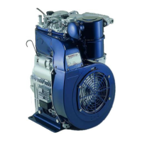
Alternator battery charger graph (12V, 12A)
This test has been carried out after thermal stabilization at 20°C for
2 minutes at 3000 r.p.m. with constant battery voltage of 12.5V.
The value of the power supplied with reference to the curve may
change in a range between +10% and -5%.
ELECTRICAL SYSTEM