Do you have a question about the Ruida Technology RDC6442S/G and is the answer not in the manual?
General introduction to the RDC644XG control system, its features, and capabilities.
Explains the naming convention and variations within the RDC644XG controller series.
Compares the performance specifications of different RDC644XG controller models.
Provides detailed dimensions and mounting hole specifications for the main control board.
Specifies the physical dimensions and mounting details for the user interface panel.
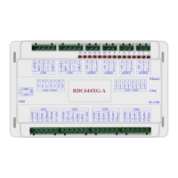
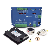
Visual identification of the main board, its connectors, and components.
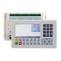
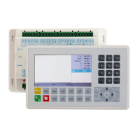
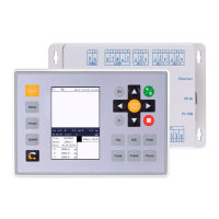
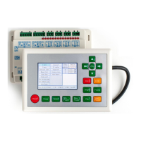
Visual identification of the control panel, its buttons, and key functions.
Illustrates the wiring schematic for connecting power, motors, and accessories.
Explains the meaning and function of the various LED indicators on the controller board.
Defines the pins and voltage specifications for the main power input connector.
Describes the pinout and connection for the Human-Machine Interface (HMI) cable.
Details the USB interface used for connecting external USB storage devices.
Specifies the USB interface for communication and data transfer with a PC.
Explains the Ethernet port for network connectivity and PC communication.
Defines the pins, symbols, and functions of the general output port CN1.
Defines the pins, symbols, and functions of the general input port CN2.
Describes the input signals for axis spacing detection on CN3 and CN4.
Details the interfaces for connecting X, Y, Z, and U axis motor drivers.
Explains the interfaces for controlling and adjusting laser power output.
Provides a general overview of the laser power control interfaces.
Shows typical wiring configurations for controlling glass tube lasers.
Illustrates typical wiring configurations for controlling RF lasers.
Introduces the principles and types of step-servo motor driver interfaces.
Demonstrates practical wiring examples for connecting step-servo motor drivers.
Illustrates input connections for various sensors and switches.
Shows output connections for controlling external devices like lamps and relays.
Explains the control panel layout, button functions, and basic operations.
Details how to navigate and adjust settings like speed, power, and layer parameters.
Covers axis movement, resets, various settings (language, IP), diagnostics, and origin setup.
Guides on managing files from internal memory and USB drives, including operations like read, copy, delete.
Describes how to interpret common alarm messages and the steps to resolve them.
Explains detailed manufacturer-set parameters for motor axes, laser configuration, and machine settings.
Details user-configurable parameters for cutting, scanning, feeding, reset, and other operational aspects.
| Brand | Ruida Technology |
|---|---|
| Model | RDC6442S/G |
| Category | Control Systems |
| Language | English |