Do you have a question about the Ruida Technology RDC6432G and is the answer not in the manual?
Details product certifications including CE, ROHS, and FCC compliance.
Explains hazard levels (Dangerous, Warning, Cautious, Important) and their meanings.
Sign indicates laser radiation, requiring caution during use with laser output equipment.
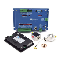
Introduces the RDC6432G system, its features, stability, and key components.
Provides physical dimensions and mounting specifications for the mainboard and control panel.
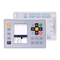
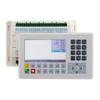
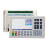
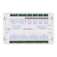
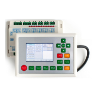
Displays visual representations of the mainboard and operator panel with labeled ports and buttons.
Illustrates the electrical connections for the control system components.
Details power, HMI, Udisk, and PC-USB interface connections.
Defines the general and dedicated output signals and their functions.
Describes dedicated/general input interfaces and three-axis limit input interfaces.
Explains the signal interface for the X, Y, and U axis drives.
Details the interface for controlling laser power, including enable and PWM signals.
Provides an overview of the control system's laser power interfaces.
Illustrates wiring diagrams for glass tube and RF CO2 laser power connections.
Explains the optocoupler isolation technology for stepper motor driver inputs.
Shows the wiring diagram for connecting stepper motor drivers to the controller.
Provides wiring examples for the controller's input ports.
Provides wiring examples for the controller's output ports.
Introduces the HMI panel and describes the function of its buttons and interface.
Explains the HMI main interface and guides basic parameter settings like speed, power, and layers.
Lists the main menu options available on the HMI.
Explains settings for jog, pulse, and axis reset functions within the menu.
Covers menu options for positioning, language selection, and system diagnosis.
Details viewing system information and managing parameters like backup and restore.
Explains U disk operations, time setting, IP configuration, and Z-axis stop settings.
Introduces the file management system for storing and accessing job files.
Covers memory file handling, array information, and feeding parameter setup.
Details memory formatting and managing files on a U disk.
Covers password input, system prompts, alarms, and general parameter setting methods.
| Input Voltage | 24V DC |
|---|---|
| Communication Interface | USB, Ethernet |
| Supported Motors | Stepper, Servo |
| Compatible Software | RDWorks |
| Processor | DSP |
| Operating System | Embedded |
| Control Type | DSP |
| Max Servo Motor Drive | 4-axis |
| Laser Control Signal | PWM |
| Axis | 4-axis |
| Supported File Formats | PLT, DXF, AI, BMP |
| Operating Temperature | 0-50°C |