RDC6432G control system user manual V1.1
SHENZHEN RUIDA TECHNOLOGY
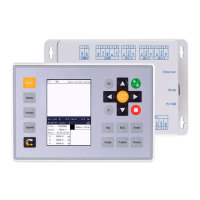
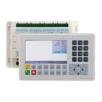
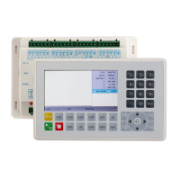
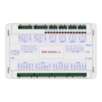
4.1 Main power connector POWER
This control system uses a single 24V power supply. In order to
leave a certain margin, it is recommended to choose a power
supply of 24V / 2A or more. At the same time, the control system
is compatible with 36V power supply, that is, the driver's 36V
power can be directly connected to the main power interface of
the control system, but this is not recommended.
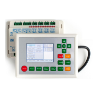
4.2 Mainboard and display connector HMI
The connection line between the mainboard and the display should be a parallel line of PIN to
4.3 Udisk Interface
U disk is the USB-AM interface, which is the interface for the mainboard to access the U disk.
4.4 PC-USB Interface
PC-USB is a communication port that can build up the communication between the controller
and the computer. It supports USB2.0 protocol.
24V power positive (input)