Do you have a question about the Ruida Technology RDV6442G and is the answer not in the manual?
Product certified by CE (Commutate European) safety certification.
Product certified by EU legislation (Restriction of Hazardous Substances).
Product certified by Federal Communications Commission for safety.
Indicates a serious danger; may cause serious injury or death.
Indicates potential danger; may lead to personnel injury.
Represents potential product risk; may cause damage to the product.
Provides important operational help and information.
Information regarding products with laser output and safety precautions.
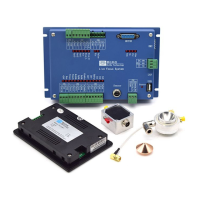
Introduction to the RDC644XG system and its features.
Details on the controller model and its variations.
Compares performance features of different controller models.
Specifies dimensions and mounting hole details for the mainboard.
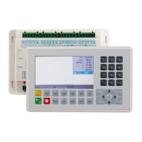
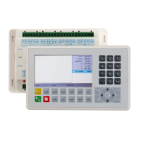
Provides the physical dimensions for the control panel.
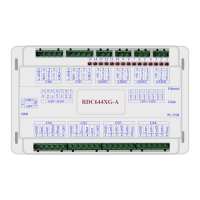
Visual representation of the mainboard and its connectors.
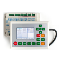
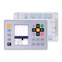
Visual representation of the control panel buttons and layout.
Illustrates the electrical wiring and connections for the system.
Explains the meaning of various LED indicators on the mainboard.
Details of the main power source connection and pin definitions.
Information on the connection between the panel and the mainboard.
Description of the USB interface for Udisk connectivity.
Description of the USB interface for PC communication.
Details on the 10/100MHZ Ethernet communication port.
Pin definitions and functions for the general output port.
Pin definitions and functions for the general input port.
Details of the interface for 4-axle spacing input.
Interface specifications for controlling X, Y, Z, U axis motor drivers.
Interface for controlling laser power, with two digital interfaces.
Overview of the two independent digital laser power control interfaces.
Wiring example for controlling glass tube laser power.
Wiring example for controlling RF laser power.
Explanation of the input signal technology for step-servo motor drivers.
Illustrates wiring examples for connecting motor drivers.
Illustrates input connection examples for IO ports.
Illustrates output connection examples for IO ports.
Overview of the control panel, its layout, and individual keys.
Description of the main operational interface and its components.
Details on the Z/U key's functionality and sub-menus.
Details on the File key's functionality for file management.
Introduction to common alarm information and handling.
Explanation of parameters set by the manufacturer for machine operation.
Explanation of parameters that users can adjust for operation.
| Brand | Ruida Technology |
|---|---|
| Model | RDV6442G |
| Category | Control Systems |
| Language | English |