RDV6442G Control System manual V1.3
SHENZHEN RUIDA TECHNOLOGY
motion axle leaves the spacing position, it will trigger a high-level signal or disconnect the spacing signal
so as to make the spacing indicator go out, but when it leaves the spacing, the corresponding indicator
will light and the spacing polarity become positive. The mistaken setting of spacing polarity will result that
the spacing can’t be detected when the system is reset so as to lead to the collision of axles.
The pin definitions of Z/U axle spacing input CN3 are the same as CN4.
All XYZU axle spacing inputs are compatible to 5V/12V/24V logic level inputs.
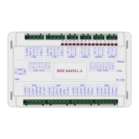
4.9 X/Y/Z/U axle Motor Driver Interface AXIS_X~AXIS_U
The interfaces of the above four motion axles are the same. The AXIS-X interface is exampled.
Directional signal (OC output)
5V Power positive (output)
The polarity of directional signal for driver pulse signal can be set. Where a certain axle is reset, it will
move to the opposite direction of machine origin, which means the polarity of directional signal for this
axle is not correct. In such a case, the connection between this axle and the motor driver can be broken
first (otherwise the mainboard can not be detected to the spacing so as to lead to the collision of this
axle), and then such a polarity can be corrected after this axle is reset completely. Upon the correction,
the reset key can be pressed against to reset the mainboard.
And, the Pulse signal can be falling edge valid or rising edge valid. The default setting is falling edge
The Pulse signal and the directional signal are all OC outputs. The
Controller must be common anode with the motor driver.
4.10 Laser Power Control Interface CN5/CN6
This control system has two independent and adjustable digital laser power control interfaces.
Signals of the two interfaces are similar and the first digital interface (CN5) is hereby exampled:
Laser-enabled control interface
1. When the laser is the RF laser, this pin will not be used;
2. When the laser is a glass tube, if the used laser is outputted in the