Do you have a question about the Ruida Technology RDC6445G and is the answer not in the manual?
Product certified by CE safety certification per EU directive.
Product certified by EU legislation (RoHS) for environmental regulations.
Product certified by FCC for electronic safety regulations.
Overview of RDC6445G system for laser engraving/cutting, developed by RD Co., Ltd.
Explains the RDC6445G controller model and its different editions or sub-models.
Compares performance features of RDC6445G with other RD controller models.
Details the installation dimensions for the MainBoard in millimeters.
Provides the physical dimensions of the control panel in millimeters.
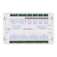
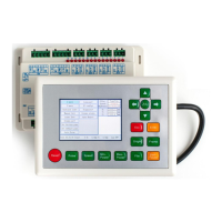
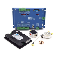
Displays the physical layout and connectors of the RDC6445G MainBoard.
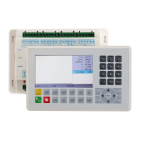
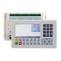
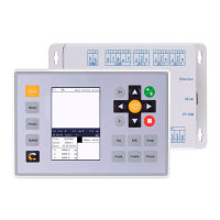
Illustrates the physical layout and components of the RDC6445G control panel.
Diagrams the electrical connections for various components of the RDC6445G system.
Details the function and meaning of the fifteen red LED indicators on the controller.
Details the pin definitions and specifications for the main power source input (CNO).
Explains the connection for the signal cable between the panel and the mainboard.
Details the USB interface used for connecting U disks to the controller.
Details the USB interface for communication between the controller and a PC.
Details the Ethernet interface for network communication with a PC.
Details the pin definitions and functions of the general output port CN1.
Details the pin definitions and functions of the general input port CN2.
Describes the spacing input interfaces for 4 axles (CN3/CN4).
Details the interface connections for X, Y, Z, and U axle motor drivers.
Details the interface connections for controlling laser power (CN5/CN6).
Provides a brief introduction to the system's digital laser power control interfaces.
Illustrates wiring examples for connecting glass tube laser power supplies.
Illustrates wiring examples for connecting RF laser power supplies.
Introduces the step-servo motor driver interfaces and their signal types.
Illustrates wiring examples for connecting step-servo motor drivers.
Demonstrates input wiring examples for various I/O ports.
Demonstrates output wiring examples for various I/O ports.
Provides an overview of the RDC6445G HMI control panel features and functions.
Explains the function of each key on the control panel.
Details the components and layout of the controller's main interface screen.
Instructions on how to set and modify the speed parameters for the machine.
Instructions on setting the maximum and minimum power levels for operation.
Guide on setting parameters for different layers within a file.
Overview of the available functions accessible through the main menu.
Instructions for accessing and modifying user-defined operational parameters.
Instructions for accessing and modifying manufacturer-specific operational parameters.
Guide on setting and managing multiple origin points for machine operation.
Instructions on how to backup the system's current parameters.
Instructions on how to restore factory default parameters.
Accessing the main settings menu for the controller.
How to select and set the display language for the control interface.
How to set the origin position of the display screen for graphics.
Configuration options related to the wireless control panel functionality.
How to configure the IP address for network communication.
Displays information about the controller's system status and version.
Accessing system functions like axis reset, laser settings, etc.
Instructions for resetting the machine's axes to their origin points.
How to lock and unlock the control panel keyboard for safety.
Performing manual adjustments and settings for machine operation.
Configuring parameters related to laser mode and operation time.
Performing system diagnostics to check hardware IO status.
Viewing detailed information and status of the laser power supply.
Managing operational files stored on the controller or U disk.
Operations related to managing files stored in the system's memory.
Performing various operations on memory files like clearing counts or copying.
Formatting the controller's memory for data management.
Managing files stored on a connected U disk.
Procedures for entering and setting system passwords for security.
Display and understanding of system prompts and alarm messages.
Instructions on how to use the automatic focusing function.
Explanation of parameters set by the manufacturer for machine configuration.
Explanation of parameters that users can adjust for specific cutting or scanning tasks.
| Control Type | Digital |
|---|---|
| Input Voltage | 24V DC |
| Communication Interface | USB, Ethernet |
| Axis | 4-axis |
| Supported Motors | Servo motor |
| Control Signal | PWM |
| Laser Control Signal | Analog 0-5V |
| Display | LCD |
| Supported File Formats | PLT, DXF, AI, BMP, DST |
| Operating Temperature | 0°C to 45°C |
| Humidity | 10%-90% non-condensing |