RDV6442G Control System manual V1.3
SHENZHEN RUIDA TECHNOLOGY
The input signal end of step-servo motor driver employs the light-coupled isolation technology. For the
step-by-step impulse signal, some isolate the side OC diode from cutoff to conduction (e.g. the valid
falling edge of pulse signal inputted from the diode minus end) and some do so from conduction to cutoff
(e.g. the valid rising edge of pulse signal inputted from the diode minus end).
When it is indicated whether the pulse signal of motor driver is the valid rising edge or the valid falling
edge, it will be subject to the pulse signal inputted from the minus end of side OC diode.
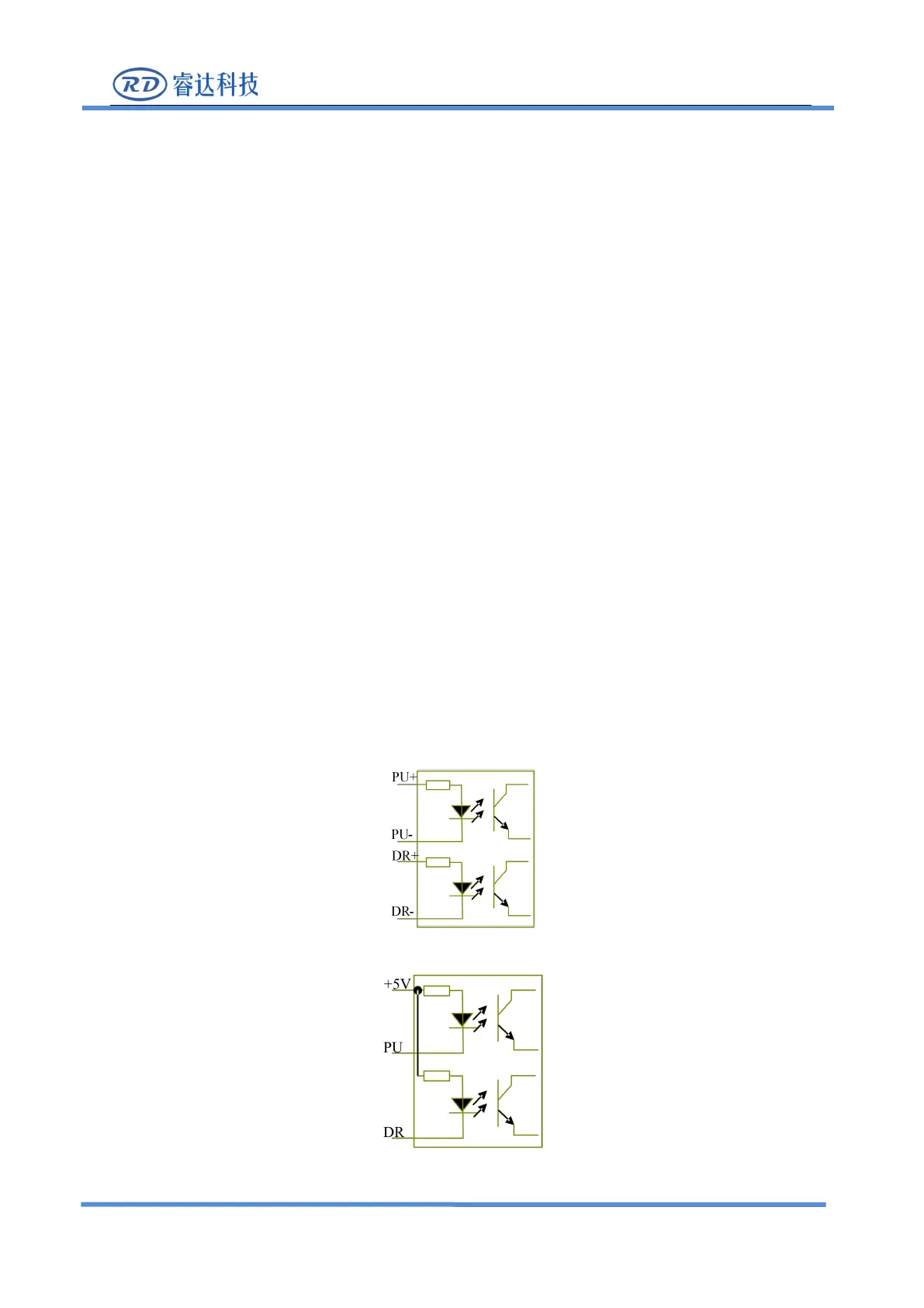
Some input signals of motor driver are independent and some are internally of common anode, so some
have 4 external leading-out wires and some 3 wires (only the pulse and directional signals are counted) as
shown in Figure 6.1-1 and 6.1-2.
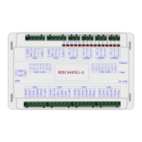
RDC644XG Controller has four groups of 3-wires motion driver interface, each interface has one direction
signal, one pulse signal, and one 5V positive output, the direction signal and the pulse signal are all OC
RDC644XG controller must be common anode with the motor driver. The polarity of the direction signal
can be changed in the factory parameters, and the valid edge of the pulse signal can also be changed.
Figure: 6.1-1 Four Inputs, Independent Input Signal of Driver
Figure: 6.1-2 Three Inputs, Common-anode Input Signal of Driver