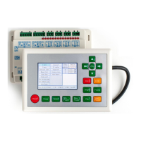
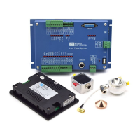
RDC6432G control system user manual V1.1
SHENZHEN RUIDA TECHNOLOGY
Contents
Section 1 Overview
.......................................................................................................................................
1
1.1 RDC6432G Control System Introduction
............................................................................................
1
Section 2 Installation dimensions
................................................................................................................
2
2.1 Mainboard installation size
................................................................................................................
4
2.2 Panel mounting dimensions
...............................................................................................................
5
Section 3 Physical maps and interfaces
.......................................................................................................
6
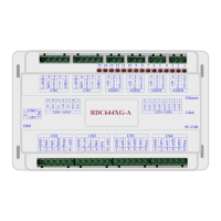
3.1 Picture of mainboard
.........................................................................................................................
7
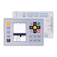
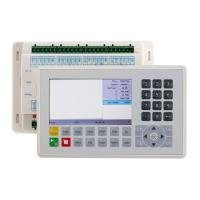
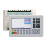
3.2 Picture of panel
..................................................................................................................................
8
3.3 Control system electrical connection diagram
..................................................................................
9
Section 4 Mainboard Interface Signal Description
....................................................................................
10
4.1 Main power connector power
.........................................................................................................
11
4.2 Mainboard and display connector HMI
...........................................................................................
11
4.3 Udisk interface
.................................................................................................................................
11
4.4 PC-USB interface
..............................................................................................................................
11
4.5 General/dedicated OUTPUT
.............................................................................................................
12
4.6 Dedicated/ General input interface INPUT
......................................................................................
13
4.7 Three-axis limit input interface LIMIT
..............................................................................................
13
4.8 X/Y/U Three-axis drive interface AXIS_X~AXIS_U
............................................................................
14
4.9 Laser power control interface
..........................................................................................................
15
Section 5 Examples of Laser Power Interface
............................................................................................
16
5.1 Overview
..........................................................................................................................................
17
5.2 Diagram of glass tube laser power connection
...............................................................................
18
5.3 RF CO2 laser wiring diagram
............................................................................................................
19
Section 6 Example of Stepper Motor Driver Interface
..............................................................................
20
6.1 Overview
..........................................................................................................................................
21
6.2 Drive connection diagram
................................................................................................................
22
Section 7 IO Port Wiring Example
..............................................................................................................
23
7.1 Input port
.........................................................................................................................................
24
7.2 Output port
......................................................................................................................................
25
Section 8 HMI operation instructions
........................................................................................................
26
8.1 HMI introduction
..............................................................................................................................
27
8.1.1 Key function description
...........................................................................................................
28
8.1.2 Main interface function
............................................................................................................
29
8.2 Speed Setting
...................................................................................................................................
30
8.3 Power setting
....................................................................................................................................
31
8.4 Layer function
...................................................................................................................................
31
8.5 Menu function
..................................................................................................................................
32
8.5.1 Jog settings
................................................................................................................................
33
8.5.2 Pulse setting
..............................................................................................................................
34
8.5.3 Axis Reset
..................................................................................................................................
34