RDC6432G control system user manual V1.1
SHENZHEN RUIDA TECHNOLOGY
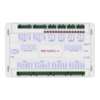
4.9 Laser power control interface
Laser power ground (output)
Laser enable control interface
1.When the laser is a RF laser, this pin is reserved
2. When the laser is a glass tube, if the laser power is low-voltage
output, then this pin is connected to the laser power laser enable
end to control the laser on/off; high- voltage laser power is not
supported.
Laser/tube power control interface
1. When the laser is a RF laser, this pin is connected to the laser
RF-PWM terminal.
2. When the laser is a glass tube, this pin is connected to the PWM
end of the laser power supply to control the power of the laser.
The first laser power supply water protection status input port.
When the water protection 1 is enabled, the main board will detect
the water protection 1 input port. If the port is in low-voltage, it is
normal. If the port is in high-voltage, the mainboard will force the
laser to be turned off, and the ongoing work will Pause, and the
system will alarm at the same time. If water protection 1 is not
enabled, the mainboard will not detect the water protection 1
input port, at this time the user cannot connect the water
protection 1.
The water protection input port must use 24V logic level input.
Laser power analog signal output. If it is a glass tube laser power
supply, this pin is recommended for the power signal.
Please select the correct laser type in the factory parameter settings.