EasyManua.ls Logo

RuiDeng DPH5005 - User Manual

RuiDeng DPH5005
14 pages
Print Icon
To Next Page IconTo Next Page
Loading...
Hangzhou Ruideng Technology Co., Ltd.
OPERATING MANUAL
DPH5005 Digital Power Supply Upper Computer
(For Win7 and above)
1 Communication Board Connetion
1.1 Wire Communication Board Connection
Open data package, double click CH341SER.EXE and install drive
program of communication board.
After installation, please use the attach cable to connect
digital power supply with communication board, and use USB cable to
connect Micro UBB port with PC.
Digital power supply communication data setting:
Keep pressing ↑button to power on, then enter into data setting
interface. Press ↑or↓ to choose data, then press knob to adjust the
value. After adjustment, press twice shortly SET key to exist data
setting, and those data are stored automatically.
COMM: Communication stitch setting, ON represents opening
communication, OFF represents closing communication.
ADDR: Digital power supply address code, range 001-255.
BAUD: Communication baud rate, 2400,4800,9600,19200 adjusting.
BPIN: Bluetooth PIN Code Pairing, 0000-9999, useless for wire
communication.
Question and Answer IconNeed help?

Do you have a question about the RuiDeng DPH5005 and is the answer not in the manual?

Summary

Communication Board Connection

Wire Communication Board Connection

Guides on installing drivers and connecting the power supply via cable to the communication board and PC.

Digital Power Supply Communication Data Setting

Details how to configure communication parameters like COMM, ADDR, and BAUD on the digital power supply.

Bluetooth Communication Board

Bluetooth Communication Board Setup

Explains connecting the digital power supply via a Bluetooth 2.0 module and pairing it with a PC.

Upper Computer Software Installation

Software Operation

MODBUS Communication Protocol

Protocol Overview

Introduces MODBUS RTU for serial and Bluetooth, listing supported function codes.

Communication Protocol Description

Explains Modbus-RTU message structure, data frame, address, and function fields.

Address Field

Defines the 8-bit slave address field (1-255) for device identification.

Function Field

Describes the Function Code field and supported codes: 0x03, 0x06, and 0x10.

Data Area and Register Map

Details the data area structure and provides a register map for device parameters and control.

Error Checking and CRC Calculation

Explains the Cyclic Redundancy Check (CRC) method for error detection in RTU communication.

MODBUS Communication Examples

Reading Voltage and Current (Function 0 x03)

Shows message format for reading output voltage and current using MODBUS Function Code 0x03.

Setting Voltage (Function 0 x06)

Illustrates message format for setting the output voltage to 24.00V using MODBUS Function Code 0x06.

Setting Voltage and Current (Function 0 x10)

Demonstrates message format for setting voltage and current values using MODBUS Function Code 0x10.

Overview

This document describes the DPH5005 Digital Power Supply Upper Computer, designed for use with Windows 7 and above operating systems. It covers both wired and Bluetooth communication methods, software installation, and operational procedures, including a detailed communication protocol.

Function Description

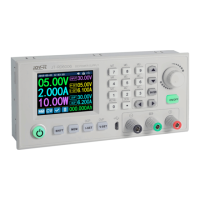
The DPH5005 Digital Power Supply Upper Computer is a software interface designed to control and monitor the DPH5005 Digital Power Supply. It allows users to remotely set voltage and current, manage data groups, perform automatic tests, and conduct voltage and current scans. The system supports communication via a wired connection (USB to communication board) or Bluetooth. The communication protocol is based on MODBUS RTU, enabling robust and standardized data exchange between the computer and the power supply.

Important Technical Specifications

  • Communication Interface: Wired (USB to communication board) and Bluetooth 2.0 protocol.
  • Operating System Compatibility: Windows 7 and above.
  • Communication Protocol: MODBUS RTU.
  • Supported MODBUS RTU Function Codes: 0x03 (Read Holding Register), 0x06 (Write Single Register), 0x10 (Write Multiple Registers).
  • Serial Data Format: 10-bit binary system (1 start bit, 8 data bits, no parity bit, 1 stop bit).
  • Data Frame Structure: Data-frame interval of 3.5 bytes or more, 1-byte address code, 1-byte function code, N-byte data area, 2-byte CRC Check.
  • Address Field: 8 bits, range 1 to 255. Each slave must have a unique address.
  • Baud Rates: 2400, 4800, 9600, 19200 (adjustable).
  • Bluetooth PIN Code: 0000-9999 (default 1234 for pairing).
  • Communication Interface Power Supply: DC 3.3V (limited power ability).
  • Register Map:
    • U-SET (Voltage setting): 2 bytes, 2 decimal places, V, R/W, address 0000H.
    • I-SET (Current setting): 2 bytes, 3 decimal places, A, R/W, address 0001H.
    • UOUT (Output voltage display value): 2 bytes, 2 decimal places, V, R, address 0002H.
    • IOUT (Output current display value): 2 bytes, 2 decimal places, A, R, address 0003H.
    • POWER (Output power display value): 2 bytes, 1 or 2 decimal places, W, R, address 0004H.
    • UIN (Input voltage display value): 2 bytes, 2 decimal places, V, R, address 0005H.
    • LOCK (Key lock): 2 bytes, 0 decimal places, R/W, address 0006H.
    • PROTECT (Protection status): 2 bytes, 0 decimal places, R, address 0007H.
    • CV/CC (Constant Voltage / Constant Current status): 2 bytes, 0 decimal places, R, address 0008H.
    • ONOFF (Switch output state): 2 bytes, 0 decimal places, R/W, address 0009H.
    • B_LED (Backlight brightness level): 2 bytes, 0 decimal places, R/W, address 000AH.
    • MODEL (Product model): 2 bytes, 0 decimal places, R, address 000BH.
    • VERSION (Firmware Version): 2 bytes, 0 decimal places, R, address 000CH.
    • EXTRACT_M (Shortcut to bring up required data set): 2 bytes, 0 decimal places, R/W, address 0023H.
    • S-OVP (Over-voltage protection value): 2 bytes, 2 decimal places, V, R/W, address 0052H.
    • S-OCP (Over-current protection value): 2 bytes, 3 decimal places, A, R/W, address 0053H.
    • S-OPP (Over power protection): 2 bytes, 1 decimal place, W, R/W, address 0054H.
    • M-PRE (Memory Preset Number): 2 bytes, 0 decimal places, R/W, address 0056H.
    • S-INI (Power output switch): 2 bytes, 2 decimal places, R/W, address 0057H.
  • Data Groups (M0-M9): User programmable, each storing preset values. M0 is the power-on default. M1 and M2 are shortcut groups. M3-M9 are ordinary storage groups. Each group's start address is calculated as 0050H + (Data group number * 0010H).
  • Key Lock Function: 0 = not locked, 1 = locked.
  • Protection Status: 0 = good running, 1 = OVP, 2 = OCP, 3 = OPP.
  • Constant Voltage/Current Status: 0 = CV, 1 = CC.
  • Output Control Function: 0 = closed, 1 = open.
  • Backlight Brightness Level: 0 = darkest, 5 = brightest.
  • Error Checking: Cyclical Redundancy Check (CRC) method (16-bit binary value).

Usage Features

  1. Communication Board Connection:

    • Wired: Connect the digital power supply to the communication board using the provided cable. Connect the Micro USB port of the communication board to the PC using a USB cable. Install the CH341SER.EXE driver.
    • Bluetooth: Connect the digital power supply to the Bluetooth communication board. After power-on, the LED on the Bluetooth board will blink, indicating it's in search mode. On the PC, open Bluetooth settings, right-click the Bluetooth icon, and select "add device." The device will appear as "DPH5005_XXX" (where XXX is the address code). Enter the default pairing code (1234). The system will automatically download and install the Virtual Serial Port driver. The smaller COM port number (e.g., COM3) should be selected in the upper computer software.
  2. Digital Power Supply Communication Data Setting:

    • To enter the data setting interface, press and hold the "↑" button while powering on the device.
    • Use "↑" or "↓" to select data, then press the knob to adjust the value.
    • Press the SET key twice shortly to save settings and exit.
    • COMM: Communication switch (ON/OFF).
    • ADDR: Digital power supply address code (001-255).
    • BAUD: Communication baud rate (2400, 4800, 9600, 19200).
    • BPIN: Bluetooth PIN Code (0000-9999), not used for wired communication.
  3. Upper Computer Software Installation:

    • Open the data package and unzip the software.
    • Double-click setup.exe to start the installation.
    • Follow the on-screen prompts, selecting the installation directory, and click "Next" to complete the installation.
  4. Software Operation:

    • Double-click the shortcut icon on the desktop to open the software.
    • In the software, select the correct serial port (COM port), baud rate, and slave address.
    • Click "Connect" to establish communication. Once connected, the digital power supply's buttons will be locked.
    • Click "Open" to enable the digital power supply output.
    • Basic Function: Set voltage and current, quickly recall data groups, and adjust brightness.
    • Advanced Function: Read and write data groups, perform automatic tests, and conduct voltage/current scans.

Maintenance Features

  • Driver Installation: The CH341SER.EXE driver is essential for wired communication. For Bluetooth, the system automatically installs the virtual serial port driver upon successful pairing.
  • Communication Data Adjustment: If communication data needs adjustment, disconnect Bluetooth from the PC first (LED will blink). This prevents accidental changes to the Bluetooth board's data.
  • System Compatibility: Ensure an official version of the computer operating system is used. Pirated or lite versions may lack necessary Bluetooth virtual serial port drivers, preventing COM port assignment and communication.
  • Bluetooth Module Placement: Avoid placing the Bluetooth module in a metal box, as this can affect signal strength.
  • Power Supply for Communication Interface: The communication interface requires DC 3.3V. Do not connect other high-power Bluetooth or WIFI modules, as this can burn out the interface due to limited power supply capability.
  • Bluetooth Reconnection: If the digital power supply is powered off while using Bluetooth, the COM interface must be reselected to reconnect the Bluetooth module after power-on.
  • LED Indicators:
    • Blinking LED on Bluetooth module: Disconnected state.
    • Solid LED on Bluetooth module: Connected state.
  • Error Checking (CRC): The MODBUS RTU protocol includes a Cyclical Redundancy Check (CRC) field to ensure data integrity. The transmitting device calculates and appends the CRC, and the receiving device recalculates and compares it. Mismatched CRC values indicate an error. This mechanism helps maintain reliable communication by detecting corrupted messages.

RuiDeng DPH5005 Specifications

General IconGeneral
BrandRuiDeng
ModelDPH5005
CategoryPower Supply
LanguageEnglish

Related product manuals