0.01A- and 0.30A. (10mA to 300mA).
Press "Next" button to switch to the Data Connection Cable impedance Measurement Interface.
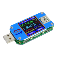
Interface 4: Data Connection Cable Impedance Measurement Interface.
The Tester can be used to measure the
resistance of a data connection cable.
14: 1. USB Tester directly connected to the
power supply with Voltage and Current
values displayed.
15: 2.USB Tester connected via a data
connection cable with Voltage and Current
values displayed.
16: R: Data Connection Cable resistance.
Measurement procedure:
First, connect the USB Tester directly to the power supply and adjust the appropriate load
current (recommended value 1A). Press and hold the "Next" button to begin recording data. The
indicator prompt will stop flashing.
Second, unplug the USB Tester and then reconnect it to the power supply via the data
connection cable and adjust the load current to the same value as in the first step. Press and hold
the "Next" button to begin recording data. The indicator prompt stops flashing and the Data
Connection Cable resistance measurement test is completed and the value displayed.
Note: If during the second step the screen turns black, this indicates that the voltage
difference is too high and the tester will enter the 4.5V power-down state. The load current
needs to be reduced. Then re-start the measurement from the first step. After the Data
Connection Cable resistance test is completed, the Tester needs to be powered off and then on
again to resume measurement.
Press the "Next" button to switch to the voltage graphing interface.
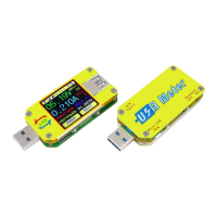
Interface 5: Voltage Graphing Interface.
This interface displays the voltage
measurement over time in the 4.5V-24.0V
range and will automatically adjust the
displayed range in real time to account for
voltage fluctuations.
Press the "Next" button to switch to the
Current graphing interface.
Interface 6: Current graphing Interface.
This interface displays the Current
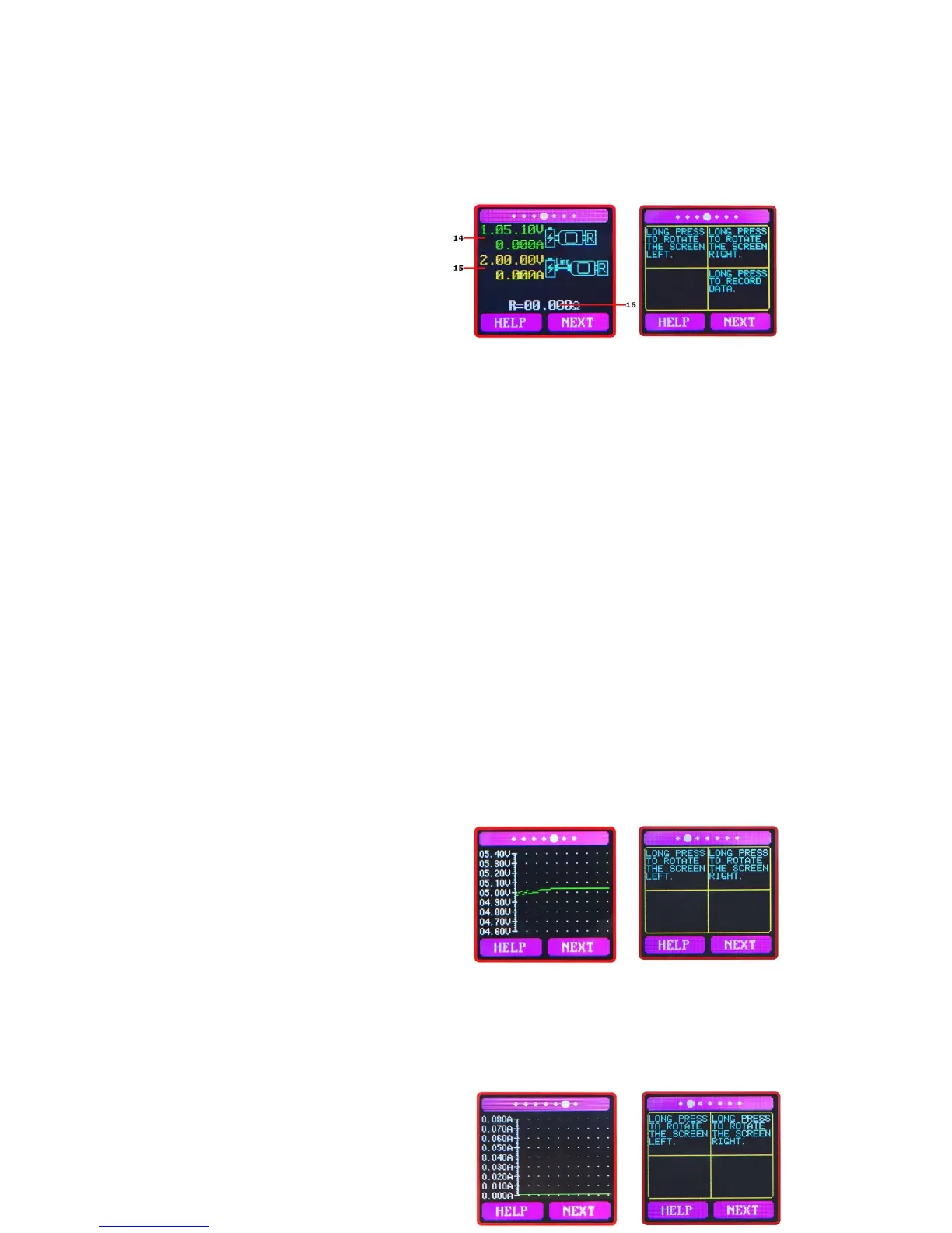 Loading...