Do you have a question about the Ruijie RG-EST310 Series and is the answer not in the manual?
Details the technical specifications of the RG-EST310 wireless bridges.
Explains the function and state of device LEDs and buttons.
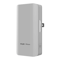
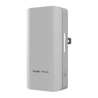
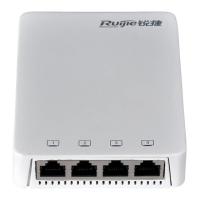
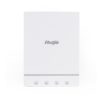
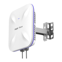
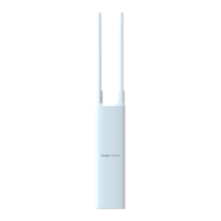
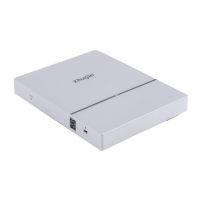
Illustrates the RG-EST310 device, showing its physical layout and ports.
Provides guidance on lightning protection measures for device installation.
Details site selection, environmental factors, and EMI considerations for proper installation.
Lists the necessary tools for installing the RG-EST310 device.
Instructions for unpacking and verifying the contents of the RG-EST310 package.
Provides a visual flowchart outlining the steps for installing the device.
Covers pre-installation verification, safety checks, and important precautions.
Step-by-step instructions for wall and pole mounting the RG-EST310 device.
Details how to connect network and power cables for the RG-EST310.
Explains the 10/100/1000 Mbps Ethernet port specifications and wiring.
Provides pin assignment details for 100BASE-TX/10BASE-T Ethernet connections.
Lists all components included in the RG-EST310 hardware package.
The Ruijie RG-EST310 Series Wireless Bridges are designed for robust and reliable video postback scenarios, offering a comprehensive solution for outdoor wireless connectivity. This hardware installation and reference guide provides essential information for users to effectively deploy and maintain these devices.
The RG-EST310 is an 802.11ac wireless bridge primarily designed for video postback applications. It operates on a 5GHz radio, delivering an access rate of 867Mbps, which is crucial for high-bandwidth video transmission. The device is built to withstand challenging outdoor conditions, featuring an IP68 design that ensures resilience against inclement weather, including cold temperatures and high humidity. This robust design significantly simplifies both installation and ongoing maintenance, making it suitable for a wide range of outdoor deployments.
The device offers flexible power supply options, supporting either 24 V PoE (Power over Ethernet) or 12 VDC. A 24 V/0.5A PoE adapter is included as a standard accessory, providing convenience and ease of power integration. It's important to note that using a PoE adapter or switch of a different model is not recommended, as it may lead to device damage.
For connectivity, the RG-EST310 is equipped with one 10/100Base-T Ethernet port that supports 24 V PoE. This allows for both data transmission and power delivery over a single cable, streamlining installation, especially in locations where power outlets are not readily available. The device also includes a Reset Button for easy system management and troubleshooting.
Status indicators are provided through a series of LEDs: one system status LED, one LAN status LED, and three RSSI (Received Signal Strength Indicator) LEDs. These LEDs offer immediate visual feedback on the device's operational status, network activity, and signal strength, aiding in quick diagnostics and alignment during installation.
The RG-EST310 is designed for straightforward installation, supporting both wall mounting and pole mounting. The installation process involves securing a mounting bracket to the desired surface (wall or pole) and then attaching the device to the bracket. For pole mounting, two clamps are threaded through the mounting bracket to ensure a secure fit. The guide emphasizes the importance of using appropriate hose clamps for poles outside the specified diameter range (35 mm to 89 mm) to prevent the device from falling.
Connecting the cables is a critical step, and the guide provides clear instructions for both video recorder end and camera end scenarios. Users need to select a cable based on the distance between the wireless bridge and the Power Sourcing Equipment (PSE). One end of the cable is plugged into the PoE port of the PoE injector, and the other end into the LAN port of the device. The LAN port of the PoE injector is then connected to the server or camera, and the PoE adapter is connected to the DC port of the PoE injector. Alternatively, the PoE adapter can be connected directly to the DC port of the device, with the LAN port connected to the server or camera. The maximum recommended distance for CAT5/6/7 cables is 100 meters. It is crucial to install the rear cover for waterproof and dustproof purposes after connecting the cables.
The device's LED indicators provide valuable real-time information:
The Reset Button offers two functions:
The RG-EST310 is designed for minimal maintenance due to its robust IP68 rating, which protects it from environmental factors. However, proper installation and adherence to environmental guidelines are crucial for its long-term performance.
Tool Kit: While the RG-EST310 does not ship with a tool kit, users will need to prepare tools such as a marker, Phillips (crosshead) screwdriver, slotted screwdriver, drill, paper knife, crimping pliers, diagonal pliers, wire stripper, network cable tester, related power and fiber cables, wrench, hammer, cable ties, ESD tools, and a multimeter.
Unpacking and Checking: Upon receiving the goods, users should carefully check against the parts list. Any discrepancies or errors should be reported to the distributor.
By following these guidelines for installation and understanding the device's features, users can ensure the RG-EST310 operates reliably and efficiently for its intended video postback applications in outdoor environments.
| Product Series | RG-EST310 Series |
|---|---|
| Power over Ethernet | 802.3af/at |
| Humidity Range | 5% to 95% (non-condensing) |
| Interface | Ethernet |
| Installation | Pole or wall mounting |
| Mounting | Pole or wall mounting |
| Weight | 0.5 kg |