Hardware Installation and Reference Guide Product Overview
49
The switch can be powered on by either one power supply module or dual power supply modules. If both power supply modules
are used, the switch works in the power redundancy mode.
At least one power supply module is required. If any slot is unoccupied, install a filler panel to enable proper airflow.
Specifications
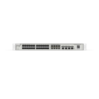
RG-S5310-24GT4XS-E, RG-S5310-48GT4XS-E, RG-S5310-24SFP4XS-E, RG-S5310-48SFP4XS-E
Rated Input Voltage Range
DC Input: -48 V DC to -60 V DC
196 mm x 50.5 mm x 40 mm (7.72 in. x 1.99 in. x 1.57 in.)
-10°C to 55°C (14°F to 131°F)
-40°C to 70°C (-40°F to 158°F)
Relative Operating
Humidity
5% to 95% RH (non-condensing)
Relative Storage Humidity
5% to 95% RH (non-condensing)
0 to 5000 m (3.11 miles) above the sea level
Features
Moisture-proof, salt spray-proof, mold-proof, insulation-proof and leak-proof
Undervoltage protection, output overcurrent protection, output overvoltage protection and output
short circuit protection
The switch can communicate with the power supply module through I2C.
System supports 1+1 power redundancy. Dual power supply modules are connected in parallel for
current sharing.
In the power redundancy mode, the power supply module can be replaced when the system is
powered on.
When a power fault occurs, the output status LED turns off.
LED
The power supply module is not outputing power properly.
The power supply module is outputing power normally.
1.13.4 RG-PA600I-P-F Module
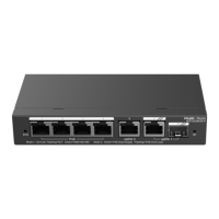
The RG-S5310-24GT4XS-P-E and RG-S5310-48GT4XS-P-E switches support the RG-PA600I-P-F power module. The RG-PA600I-P-F is an
AC module (AC/HVDC input and DC output) providing an output voltage of 56 V and an output power of up to 600 W (PoE power: 370

 Loading...