20 DRUM MOTOR INSTALLATION MANUAL 80LP-138LP
REPLACEMENT PARTS AND ACCESSORIES
Mounting Brackets
F = F1 + F2 + F3 +....
Friction
between belt
and Material
Weight (t)
Bell Pull =
•
F (N)
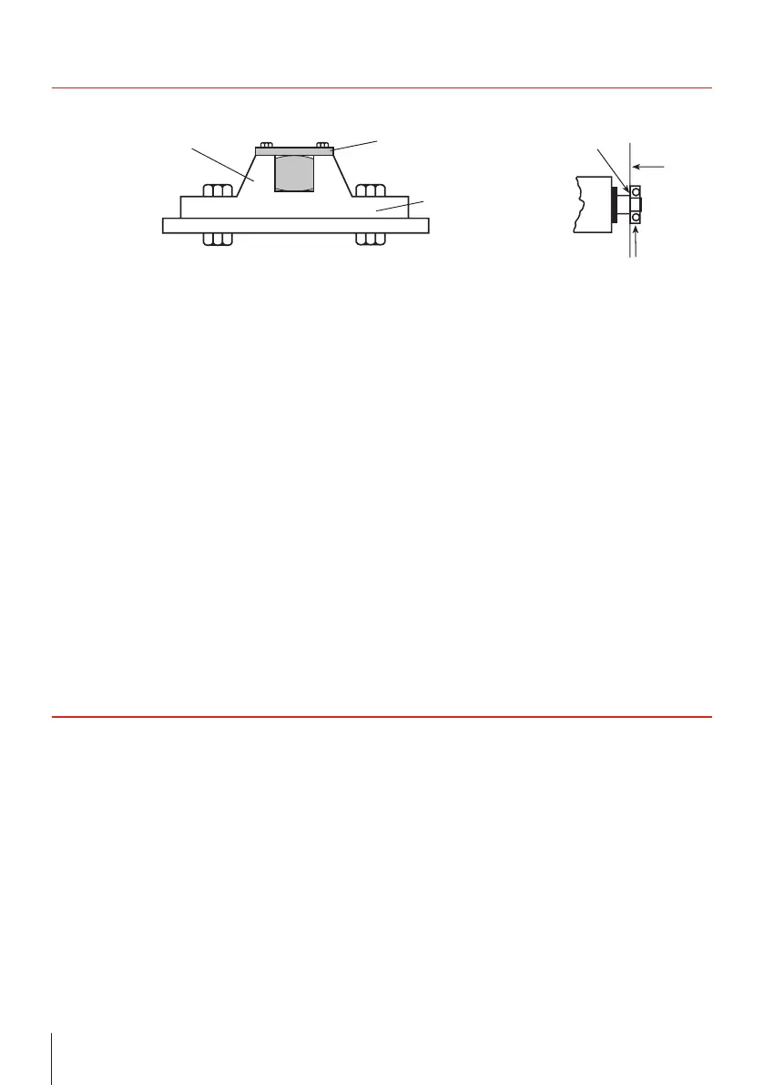
Shoulder Retaining plate
Base
Shaft shoulder
Bracket
Bracket
with key
Key
Marking of the
earth screw
R, S, T
PEN
K1
K
TP
M
3
F = F1 + F2 + F3 +....
Friction
between belt
and Material
Weight (t)
Bell Pull =
•
F (N)
Shoulder Retaining plate
Base
Shaft shoulder
Bracket
Bracket
with key
Key
Marking of the
earth screw
R, S, T
PEN
K1
K
TP
M
3
> Use only the mounting brackets that match the
respective Drum Motor type.
> Assemble mounting brackets to the frame so
that the shoulder or base resist belt tension.
When RULMECA Drum Motor mounting
brackets are NOT used, it is essential that:
• the mounting equipment supports at least 80 %
of the shaft ats.
• the clearance between the shaft ats shoulder
and the support is less than 0.4 mm (torsion
play).
• there is no clearance between the bracket and
the shaft shoulder.
A Drum Motor with frequent reversals or start/
stops should be mounted without axial clearance
between the shaft at shoulder and the bracket.
Motor Thermal Protection
All Drum Motors are supplied with a built-in thermal
protector.
• heat-sensitive, bi-metallic switches built into
each motor phase winding
• maximum permissible current 2.5 A
• voltage 230 V
> Connect the switches to the closed control
circuit (in series with a magnetic coil/relay device
and contactor)
• The switch opens if motor temperature rises to
an excessively high level.
> The motor will shut down.
• The switch will automatically close once the
motor has cooled down.
• Cooling time = 30 – 60 min at an ambient
temperature of 20 °C
> Use this period of time to identify the reason
for the shutdown.
> Do not operate the motor until the causes of
the overheating/overload have been eliminated.
Lagging
Lagging thickness and width greatly affect Pulley
heat dissipation characteristics.
Basic specications:
• Smooth, diamond pattern
• Black, white synthetic rubber
• shore hardness A = 65 or 70 durometer
• cold-bonded or hot vulcanised
Optional hot vulcanized lagging is available for high
power/high torque/high temperature applications.
> Contact the belt supplier if belt/lagging material
compatibility may be a problem.
Belt
The belt type, the belt thickness and the correct
pulley diameter must be determined according to
the belt manufacturer’s data.
Belt tension
> Do not over-tension the belt.
> Tension the belt just enough to prevent the belt
from slipping and to ensure non-slip operation.
The maximum permissible belt tension (T1 + T2) is
specied in our catalogue.
 Loading...