MODEL 82602-F79A-LCD/82602B-F79B-LCD/82604-F82A-LCD/82604B-F82B-LCD
11
c. Screw drain hose connector into drain outlet, and lock it.
d. Locate the drain hose well as the Figure1-4
shows.
Note:
●Control valve should be higher than drain
outlet, and be better not far from the drain
hose.
●Be sure not connect drain with sewer, and
leave a certain space between them, avoid
wastewater be absorbed to the water
treatment equipment, such as showed in the
Figure1-4.
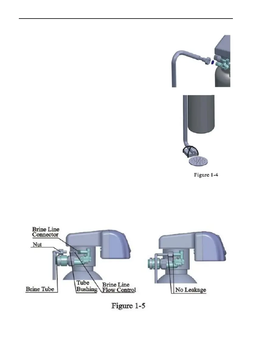
○,6 Connect brine tube
a. As Figure1-5 shows, slide 3/8″ brine tube hose
connector over end of brine tube.
b. Insert tube bushing into the end of brine tube.
c. Insert the red brine line flow control into valve
brine line connector (Attention: Cone side of
control should face into valve).
d. Tighten brine draw hose connector onto brine line connector.
e. Connect the other end of brine tube with the brine tank. (the liquid level
controller and air-blocker should be installed in the brine tank.)
Remark: The brine tube and drain pipeline should not be bended or
plugged.
 Loading...