MODEL 82602-F79A-LCD/82602B-F79B-LCD/82604-F82A-LCD/82604B-F82B-LCD
10
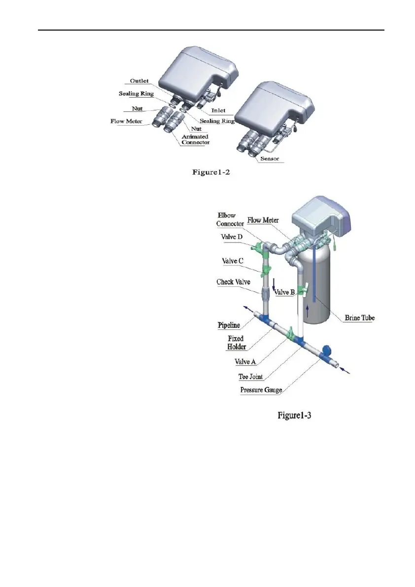
○,4 Pipeline connection
a. As Figure 1-3 shows, install a
pressure gauge in water inlet.
b. Install valve A, valve B, valve C
and valve D in the inlet and outlet
pipeline. The valve D is sampling
valve. (Or adopt F70C/F70D bypass
valve). (Can remove the check
valve.)
c. Inlet pipeline should be in parallel
with outlet pipeline. Support inlet
and outlet pipeline with fixed holder.
Note:
●If making a soldered copper
installation, do all sweat
soldering before connecting
pipes to the valve. Torch heat will
damage plastic parts.
●When turning threaded pipe
fittings onto plastic fitting, use care not to cross thread or broken
valve.
●If the valve belongs to time clock type or F79, there are no step ②
and③
○,5 Install drain pipeline
a. As the Figure 1-4 shows, slide the drain hose connector into drain outlet.
b. Insert drain line flow control into drain outlet.
 Loading...