O&M Manual –90E1720004
Section 5 Installation Page 14 of 52
Section 5 Installation
Before installing Russelectric bypass-isolation transfer switches, read and understand:
1. All precautions in this manual.
2. All manuals for associated components.
3. All drawings and diagrams included with the equipment.
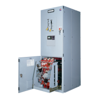
Installing the Bypass-Isolation Transfer Switch
When correctly installed the:
1. Enclosure is straight, level and perpendicular to the mounting surface.
2. The switch is fastened securely to the floor or wall.
3. The shipping sections are bolted together securely if applicable.
4. Cable and control wiring connections are connected properly.
Preparing the Site
Before positioning the equipment, check these items to ensure that the site is ready for final
installation.
1. Compare the site plans and specifications with the equipment drawings to be sure
no discrepancies exist.
2. Check the site to confirm switch will fit properly.
3. Provide area ventilation at all times to maintain the ambient temperature around
the equipment between 50 °F (10 °C) and 104 °F (40 °C).
4. Provide adequate permanent lighting and convenience outlets near the
equipment.
5. Route sewer, water, and steam lines away from the equipment.
6. Provide floor drains near the equipment.
7. When installing the equipment, consider the aisle space required at the front and
rear of the equipment as well as either side.
NOTE: Required minimum clearances around the transfer switch are given in Article 110.26
of the National Electrical Code® (NEC®). These clearances are only a minimum. Additional
space may be required for maintenance or removal of components.
Preparing the Foundation
1. Confirm that the floor or foundation is strong enough to support the equipment
without distortion or sagging.
NOTE: Refer to the shipping documents for actual weights of the equipment.
2. Confirm that the concrete is level left-to-right and front-to-rear to within 1/8-inch
per square yard.
3. Install equipment on a smooth, level base to keep tolerances and adjustments to a
minimum.
Anchoring the Switch –Non Seismic
1. Four 5/8-inch diameter holes are supplied to anchor the free standing enclosure.
Use all four mounts to anchor the switch to the foundation properly.
2. Anchor the switch to the floor (Figure 5) with four 1/2-inch Grade 2 minimum
bolts, flat washers, and anchors (not furnished) and torque to 60 ft-lbs.
 Loading...