O&M Manual –90E1720004
Section 5 Installation Page 20 of 52
Connect the Controls and Wiring
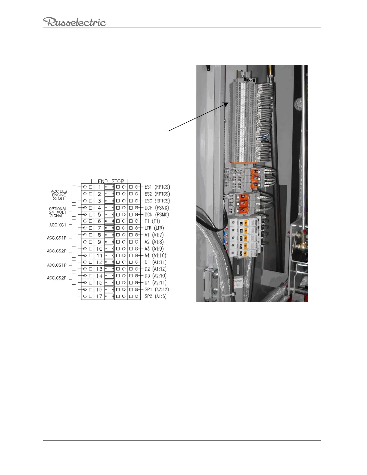
1. Locate the customer control terminal block TB5 (Figure 13) located behind the
upper door.
Figure 13: Locate the TB5 Terminal Block
2. Refer to the wiring diagrams supplied with the switch for proper field
connections to the TB5 terminal block.
Note: The TB5 terminal block has been tagged at the factory and is shown on the connection
diagrams for each installation.
3. Check control wiring with the connection diagram to confirm all connections
have been made properly and loose connections tightened properly.
Note: If the control power source is other than an internal control power transformer, the wires
from the source to the switch must be of adequate size to avoid excessive voltage drop during
operation.
TB5 Terminal
Bloc
 Loading...